Since we moved to this flat, one of my wishlist item was to have a way to control the HVAC (heat, ventilation, and air conditioning) without having to get out of bed, or go to a different room. A few months ago, I started on a relatively long journey of reverse engineering the protocol that the panel used so that I could build my own controller, and I’ve been documenting pretty much every step along the way, either on Twitter, this blog, or Twitch. As I type this, while I can’t say that the project is all done and dusted, I’ve at least managed to get to the point where I’m reaping the benefits of this journey.
You may remember that at the end of the previous chapter in this saga I was looking at controlling the actual HVAC with a Python command line tool. I built that on stream, to begin with, and while I didn’t manage to make it work the way I was hoping (with a curses-based UI), I did manage to get something that worked to emulate both the panel and (to a minor point) the HVAC itself.
I actually used this “in production” (that is, to control the air conditioning in my home office) for a little over a week. The way I was using it was through a Beagle Bone Black which I had laying around for a long while – I regret not signing up for the RISC-V preview, but honestly I wouldn’t have had time – connected through an USB-to-UART adapter (a CH340 based one, because they can actually do 104bps!), and a breadboarded TLIN1206 on a SOP-8-to-DIP adapter. A haphazard and janky setup if you’d ever seen one, but it was controllable by phone… with JuiceSSH and Tailscale.
While absolutely not ergonomic, this setup still allowed me to gain the experience needed with the protocol, in order to send the PCB design to manufacture. I did that about a week in, and as usual, JLCPCB‘s turnaround is phenomenally fast, and by the following Monday I had my boards.
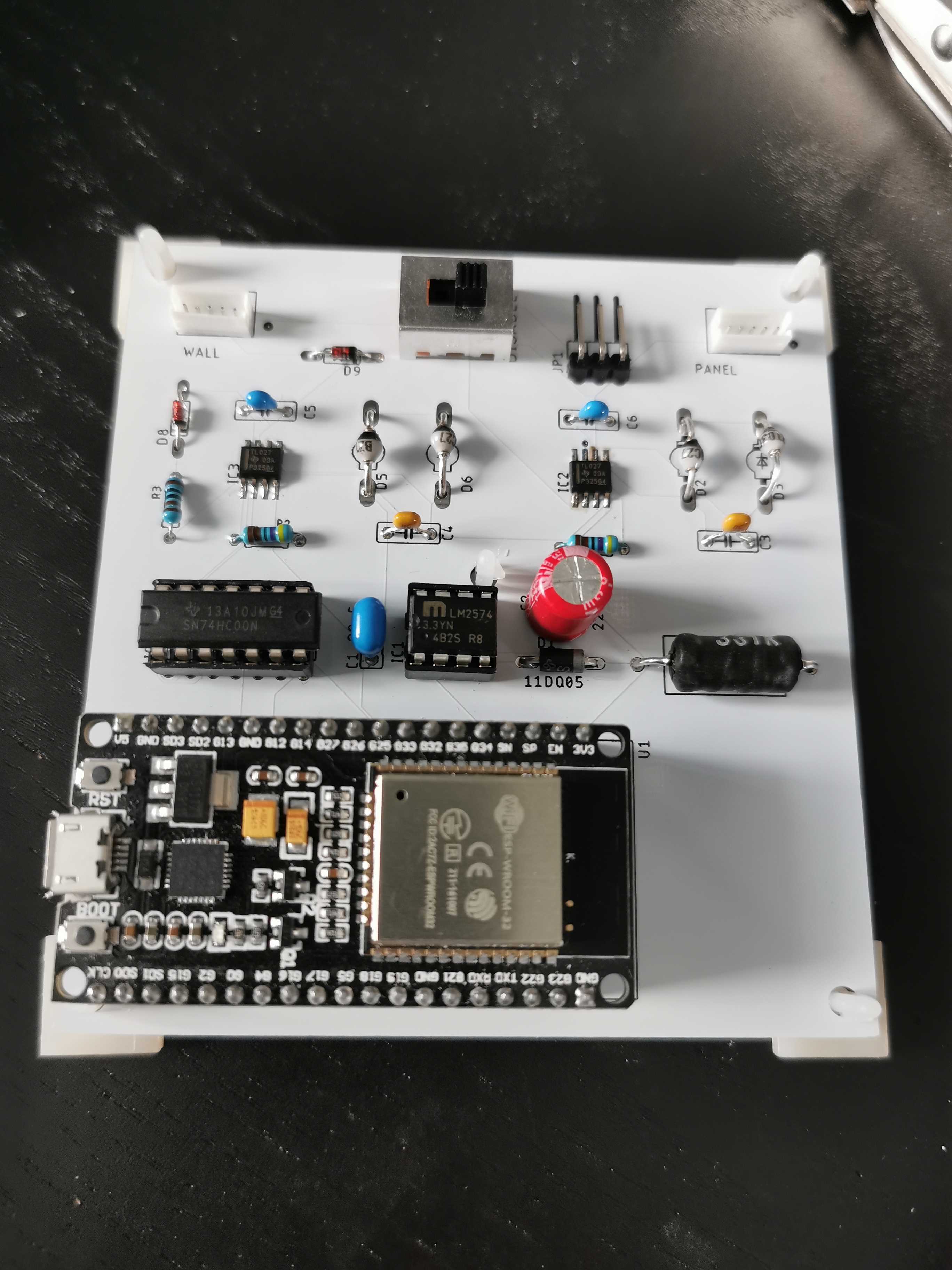
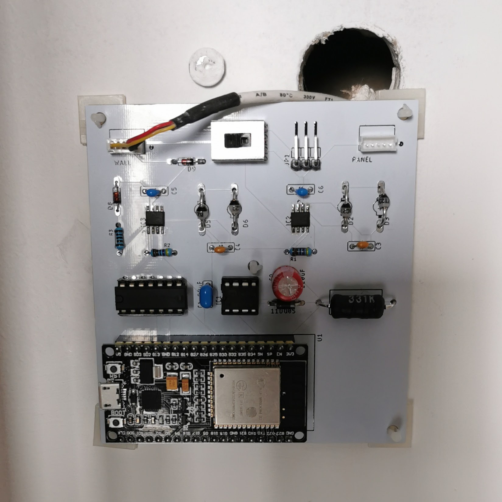
The design is pretty much the same as the one I spoke about in part two, with two bus transceiver blocks, a 3.3V DC-DC converter, the quad-NAND to make sure the code cannot send data to the bus if the physical switch is turned to “disable”.
While the design proven it needs a little bit more work to be optimal, it’s a great starting point because it just works fine. And while I did originally plan to have this support the original panel with the switch turning on “pass-through mode”, I decided that for the moment, this is not needed, nor desired.
My original intention was to allow the physical switch to just prevent the custom controller from talking to the HVAC engine, and let the original panel take over. Unfortunately this does not work: the panel is not entirely stateful, but there is a bit in the command packet that says “Listen to me, I’m changing configuration” — and if the configuration in the panel and the HVAC don’t match when that bit is not set, an error state is introduced.
This basically means I wouldn’t be able to seamlessly switch between the old panel and my custom controller. Instead what I’m going to be doing if I need to is to first flip the switch to disable the custom logic, and then connect the panel to the secondary bus. That way it would initialize directly on the bus. If I do need to re-design this board, I’m going to make the switch more useful, and add a power disconnection so that it can be all connected without power on at all.
There was another reason why I originally planned to support the original control panel: it reports a temperature. I thought that I would be able to use that temperature as a “default” sensor, while still allowing me to change the source of the temperature at the time of configuration. But the panel’s temperature sensor is pretty much terrible, and it’s only able to measure 16°C~30°C, plus it’s easily fooled by… a lamp. So not exactly something you can call reliable for this use, and not something I would care to add to my monitoring.
To my own astonishment, my first attempt at soldering the full board was successful — two out of three of the boards work like a charm, the third one is a bit iffy, but it might be a not perfect component into it. I’ll have to see, but also I don’t want to make a new respin now that even some of the components I need are getting harder (and more expensive) to find. Take the JST ZR connection: in the picture above you an see it white rather than cream — that’s because it’s not an official JST part but an AliExpress clone that fits the same footprint, and I could actually buy.
Custom ESPHome Climate
Once I had the board, I rigged up a quick test bed on my desk with a breadboard and another CH340 adapter (I have a few around, they are fairly cheap and fairly versatile), and started off to complete the Custom Climate component.
Since I started this project, the ESPHome Climate API actually changed a couple of times, particularly as Nabu Casa is now sponsoring the project, and its development moved to a monthly release kind of deal. Somehow the Climate components were among those that most required work.
But the end result is that the API was clearer, and actually easier to implement, by the time I had this ready. So I wrote down the code to generate the six bytes packets I needed to send, and ran it against the emulator… and it seemed to work fine. I had wired this with a test component in Home Assistant and I could easily change the mode, the temperature, and everything else just fine, and I could see in my emulator that it was getting the right data in just fine.
At that point I was electrified, and I thought it would just be a matter of putting it to the wall and see it work. You can imagine my disappointed when I called in my wife to assist me in my victory… and it didn’t work. And I was ready to detach all of it to spend the next day debugging what was going on, until I realized that I forgot to send the “settings changed” flag. I have to say that the protocol turns out to be a bit more complex than I expected it to be, and I should probably write a bit more documentation about it, not just scatter it around the (now multiple) implementations.
After that, I actually went ahead and replaced all three of the control panels with my custom ones, and connected them to Home Assistant. That turned out to be a much easier prospect than anything else we have been trying up to now: we can decide which temperature reading to use to control the room, rather than being stuck to the silly temperature sensor in the panel, and we can use the two-point set temperature in the way most modern smart thermostat can (which the panel didn’t support, despite having an “auto mode” that would turn on cooling or heating “as needed”).
The first couple of days lead to a bit of adjustments being necessary — including implementing a feature that my wife requested: when not cooling or heating, the original panel would enter “fan only” mode. Which I enjoy for myself in the office, but bothers my wife. The original panel does not have an option to turn the fan off — but I could implement that in the custom controller. This allows us to keep our thermostat on the heat-cool mode most of the time, and just make sure the range is what we actually care for.
I also made the mistake at first of not counting on hysteresis. That turned out to be a bit more annoying to implement, not in the matter of code, but in the matter of the logic behind it — but it should now be working: it means that there is more friction to change the state of the air conditioning, which means the temperature is not as constant, but it should be significantly easier to run. To be honest I was impressed by how stable the temperature was when I left it to short cycle…
Home Assistant Integration

This was probably the simplest part of the whole work! Nabu Casa is doing an awesome job at keeping the two projects integrated very well, and with the help of “packages” configuration, replicating the configuration for the three separate boards took basically no time.
The only problem I had was that I couldn’t seem to be able to flash the first ESPHome firmware onto my ESP32 devkits using the WebSerial support. I have used it multiple times in the past, particularly to update my BLE Bridge, which I just need to connect to my main workstation rather than the standalone power supply, to upgrade, but for the pristine ESP32 devkits it didn’t work out quite as well.
The UI is very similar to the one that Google Home exposes for Nest thermostats where they do support air conditioning. And indeed, with the addition of the Home Assistant Cloud service, the same UI shows up for these thermostats.
And at that point it was just a matter of configuring the expected range of operation, both for the “daytime” and for the “night scene”. Which is one of the reasons why I wanted to have thermostat that we can control with Home Assistant.
You see, some time ago I set up so that we have a routine phrase (“To the bedroom”) and Flic buttons in both the living room and the bedroom, that prepare us to get to bed: turn off the TV, subwoofer, air fresheners, lights everywhere except bedroom and bathroom, set the volume of the bedroom speaker for the relaxing night sound, and so on.
Recently, thanks to a new Dyson integration, it also been setting the humidifier to raise the humidity in the bedroom (it gets way too dry!), and turn on the night mode on the other purifiers, which has been a great way not just to make it easier not to forget things, but also to save us from leaving the humidifier running 24/7: it’s easier for us to keep it running overnight at a higher humidity, than trying to keep it up during the whole day.
Now, with the climate controls in place, we can also change the temperatures before going to bed, rather than turning it off, which is the only option we had before. And this is a big deal, because particularly for the living room, we don’t want it to get too scorching hot even if we’re not there: it’s where the food cupboards, among other things, and during the heatwave we exceeded the 30°C for a couple of hours every other day. Being able to select different ranges while we’re still sleeping gives us a bit more safety, without having to keep running the air conditioning overnight.
Features And Remote Control
Similarly, our scheduled morning routine, configured to go off together with the alarm clock, can scale back the range in my home office to something suitable for my work day (it can get warm fast with computers and stuff running, and the door closed for meetings), so I don’t have to over-run the office in the morning when having my first meeting: it starts automatically, and it welcomes me with a normal, working temperature for my first meeting.
The final point is that, since we can actually set a very wide range on the thermostats, and rely on much more accurate thermometers that are not restricted to the 16°C to 30°C range, we can leave the thermostat on, with a very wide range, when we’re not actually going to be at home. This is particularly interesting now that we might be able to travel again, at least to see families and friends — we don’t want to leave the air conditioning or heating running all the time, but we also want to have some safeguards against the temperature dropping or raising out of control. This became very clear when the CGG1 in our winter garden hit the 50°C ceiling it could report while we were out playing Pokémon Go and we couldn’t turn on the air conditioning at all — thankfully the worst result of that was that the body of one of the fake candles we have in the winter garden for ambiance melted… and now it looks even more realistic as a candle (it also damaged the moving flame part, but who cares.)
Now, the insulation of this flat is not great. In particular the home office tends to drop down close to freezing temperatures in the winter, because the window does not seal even when closed. This means I can’t easily follow Alec’s suggestion on energy storage. But having a bit more control on automation does make it easier to keep the temperature in the flat more stable. In the winter, I expect we’ll make sure that we keep a minimum temperature overnight to avoid having to force a much higher differential when we wake up, for instance.
There’s a few features that I have not yet implemented, and that I definitely should look into implementing soon. To start with, as soon as summer gives away to autumn, we’re likely going to want to be using the dehumidifier more — without turning on the heat pump, particularly in the living room as we cook and eat. Since the CGG1 provides humidity readings together with temperature, it means I can set up an automation that, if nothing else is running, turns the dehumidifier on if the humidity reaches a certain set point, for instance.
There’s also two switches that I have not implemented yet, but should probably do, soon. One turns on resistive heating – and this will make sense again if you watch Alec’s video on heat pumps – while the other has to do with the Plasma Filter.
What’s a plasma filter? That’s a good question, and one that I’m not sure I have the right answer for. I know that this is something that the original control panel suggests is present in our HVAC, although I have no way to know for sure (we don’t have the manual of the actual engines). The manual for the PQRCUDS0 says that «you can use the plasma function» but also states «If the product is not compatible with the Plasma function,
it will not do the Plasma function even though the indicator is turned on.» This suggests that unlike other features like the swirl/swing, it’s not part of the feature query that the panel sends at turn on.
When googling further to look for information about LG’s plasma filter, I did find another manual, for an actual unit, rather than the control panel. Not the unit we’ve got, I think, but at least an unit. And this one has a description for the plasma functionality:
Plasma filter is a technology developed by LG to get rid of microscopic contaminants in the intake air by generating a plasma of high charge electrons. This plasma kills and destroys the contaminants completely to provide clean and hygienic air.
This is quite a bit interesting — and next to this, a video from LG refers to this as a “Plasma/Ionizer”, which pretty much suggested me that this is one of Big Clive’s favourite toys: ozone generators. Which makes sense given that one of his favourites is a Sharp Plasmacluster.
Code And Next Steps
First of all, the code and the board designs are all available on my GitHub. I originally considered making this a normal component for ESPHome, but since it relies on a very custom board, it doesn’t feel like the right thing to do. It does mean I need to manually keep in mind all the various changes in APIs, but hopefully that will not take too much of my time.
As I said previously, I have not actually implemented the panel bus handler — the panel will enter into error mode if it does not get an expected reply from the HVAC engine, so connecting it right now would not work at all, except if you were to disable the actual ESP32 control. I’m likely going to leverage that behaviour to test some more error handling in the future.
I would like to put a box around the board — right now it’s literally stuck to the wall with some adhesive feet, in all three rooms. And while the fixed red LED is not too annoying overnight, it is noticeable if you wake up in the middle of the night. My original idea was to find someone who can help me 3D print a box that fits on the same posts the panel fits, and provide a similar set of posts for the original panel. But it also involved me finding a way to flip the switch without taking it down the wall.
But since figuring out 3D printing with no experience is going to take a lot of investment, I am not going to take a look at that option until I’m absolutely certain I’m not changing anything in the design. And I know I would want to change the design a little bit.
First of all, I want to have a physical cut-off for the connection — since the power to run the ESP32 module comes from the same cable controlling the HVAC, the only way to turn off the power is to disconnect the cable, right now. Having a physical switch that just disconnects the power and data would just make it easier to, say, replace the devkit module.
Similar, as I said, the panel is not that useful to keep running all the time. So instead I would change the switch implementation to keep the panel off most of the time, and only power it on when disabling the ESP32. This would also save some components, since there would be no need to have the second bus transceiver and its passives.
I’m also wondering if it would make sense to have some physical feedback and access, in addition to the Home Assistant integration and the voice assistant controls: in particular I’m considering having an RGB LED on the board to tell the current action being taken (optionally, I wouldn’t want to have that in the bedroom, as it would be way too bright) together with a button to at least turn the HVAC “soft off”.
Finally, there’s a couple of optimizations that could be done to make the board a bit cheaper. One of the capacitor is ceramic, but could be replaced with a polymer one for ⅓ of the price, and the TVS diodes pair (which were actually a legacy part of the design, recommended by the MCP2021, but not in the reference designs for the TLIN1027) could be replaced with a single integrated TVS diode — it would just be “a bit” harder to solder by hand in TO-236 packages.
These are all minor though — the main cost behind the board is actually the ESP32-DEVKIT-32D that it’s designed around. It would be much cheaper to use only the ESP32 WROOM module, and not have the USB support components on the board. But I have had bad experiences with trying to integrate that in my designs, so I’m feeling a bit sceptical of going down that route — it also would mean that a botched board sacrifices the whole module (I did sacrifice two or three of those already) unless you get very good at desoldering them (or you have a desoldering station).
So most likely it will take me a few months before I actually get to the point of trying building a 3D printed cover for it. With a bit of luck by then we’ll be back in an office at least part of the time, and I can get someone to teach me how to use the 3D printer there.
Also as a final note — the final BOM for the boards suggest that building one of them costs around £25 or so, without the case. As I said there’s a few cost saving measures that I could take for the next round — though it’s questionable, because it would require me to get more components I don’t currently have. Of course the actual cost of building three of them turned out to be… significantly higher.
I think this is the part that sometimes it’s hard to explain to people who have not had this type of experience: the BOM costs are only one of the problems you need to solve — you can really screw up a project by choosing the wrong components and bringing the BOM price too high… but a low BOM cost does not make for a cheap project to finish, particularly when you’re developing it from nowhere.
In this case, if I wanted to tally up the cost of building these custom thermostat panels, I would have to, at the very least, count the multiple orders from DigiKey from which I ordered the wrong components (like the two failed attempt at using Microchip’s LIN bus transceivers rather than the TLIN, or the discrete UARTs with their own set of passives). But then there’s the cost of having all of the various tools that were needed to get this all done. Thankfully most of those tools have been used (and sometimes abused) for different projects, but they are a good metaphor for the cost of R&D that many products need — so it makes sense that what you end up buying costs more than the “simple” expense of the BOM. So keep that in mind next time you see an open source hardware device costing more than what you expect it to.