Last month I wrote some notes about Chinese acrylic lamps, the same kind as I used successfully for my insulin reminder. As I said, I wanted to share the designs as I went along, and I do now have a public repository for what I have, although it has to be said that you shouldn’t trust it just yet: I have not managed to get this to properly turn it on. So instead, in the spirit of learning from others’ mistakes, let me show you my blooper reel.
Lesson #1: Don’t Trust The Library
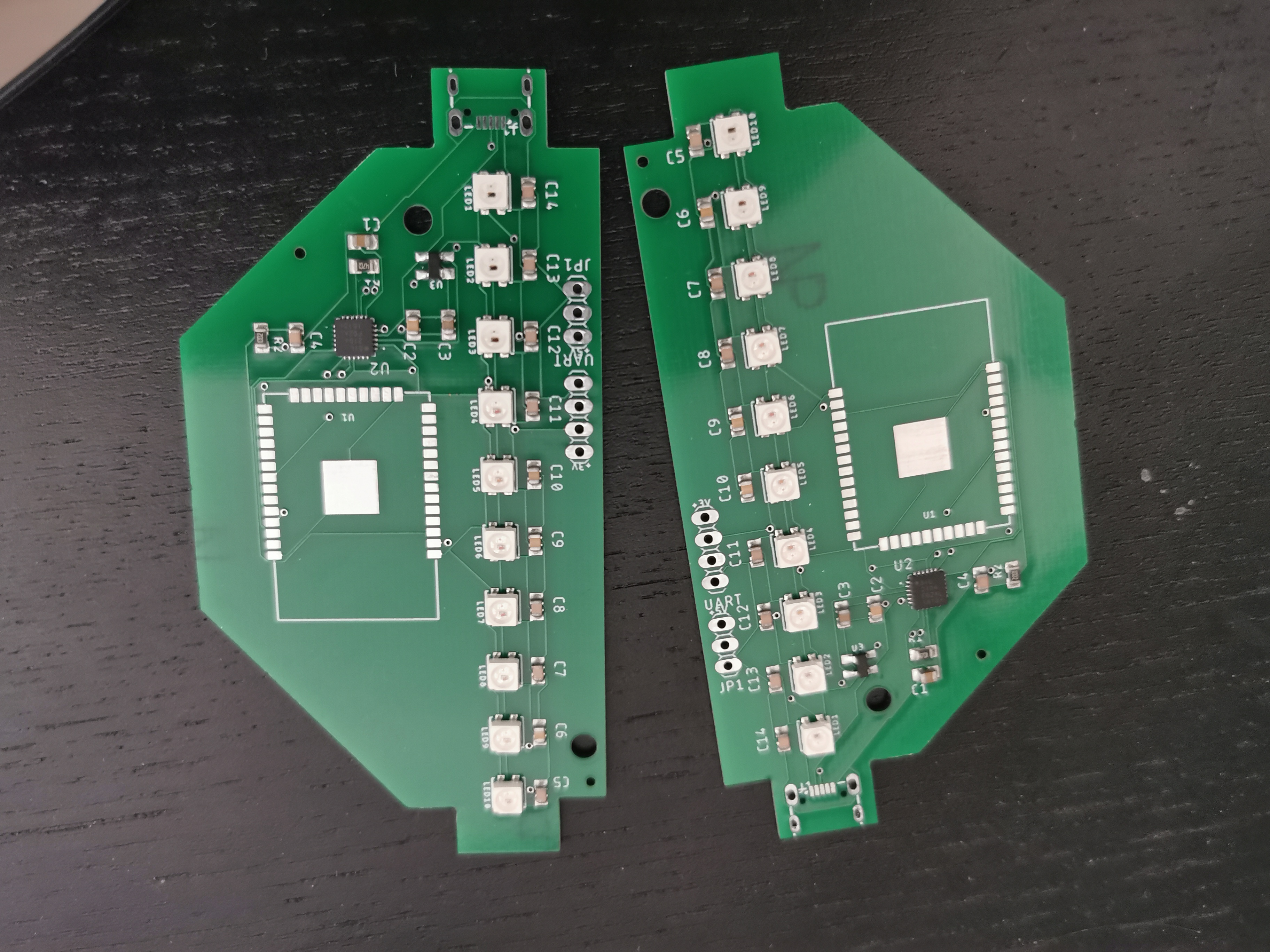
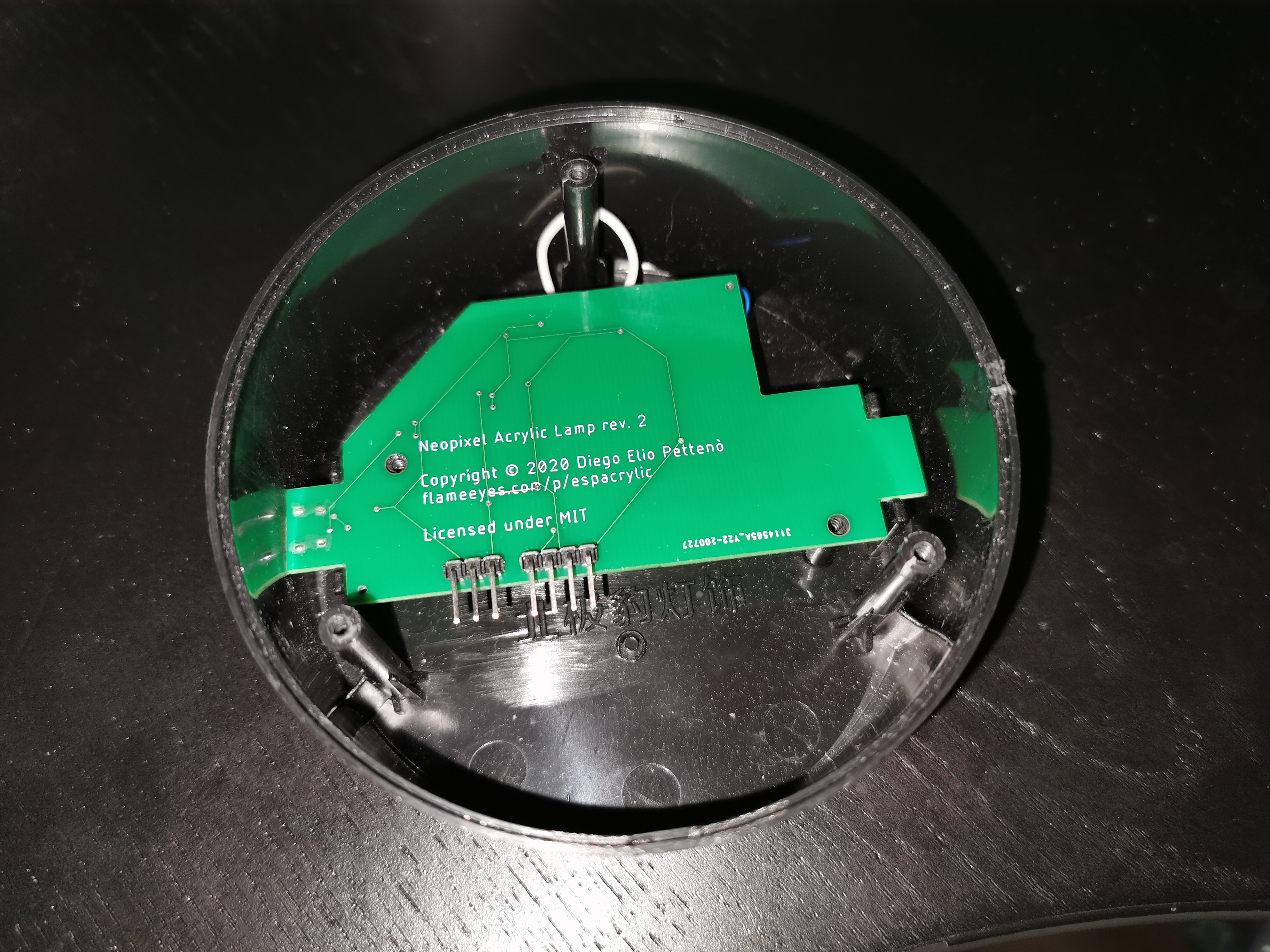
You may remember that in the previous post i showed the “sizing test”, which was a print of the board with no components on it, which I used to make sure that the LEDs and the screw holes would align correctly in the base. Since I had to take the measurement myself I was fairly worried I would get some of the measures wrong.
The size test was sent to print before I came to the conclusion that I actually wanted to use NeoPixel LEDs, instead of simple RGB LEDs, so it was printed to host “standard” 3535 common-anode LEDs. I then changed the design for a more sparse design that used the W2812B-Mini, which is a 3535 package (meaning it’s 3.5mm by 3.5mm in size), and is compatible with the NeoPixel libraries. This meant more capacitors (although modern versions of the W2812B don’t seem to require this) but less logic around connecting these up.
As you can see from the image above, I also added space on the side to solder headers to connect past the USB-to-UART and directly to the NeoPixel row. Which was probably my best choice ever. When the boards arrived, the first thing I did was connecting the NeoPixel control pins to try to turning them on and… I discovered that nothing worked.
The answer turned out to be that I trusted the Adafruit Eagle library too much: the pinout for the 3535 variants of the W2812B (the “mini”) has been added wrong since the beginning, and an issue existed since 2018. I sent a pull request to correct the pinout, but it looks like Adafruit is not really maintaining this repository anymore.
Because of the pinout mistake, there’s no way to access the NeoPixels on any of the ten boards I had printed in this batch, and I also missed one connection on the CP2104, which meant I couldn’t even use these as bulky USB-to-UART adapters as they are. But I can put this down as experience, and not worry too much about it, since it’s still a fairly cheap build by comparison with some of the components I’ve been playing with.
Lesson #2: Datasheets Can Still Lie To You
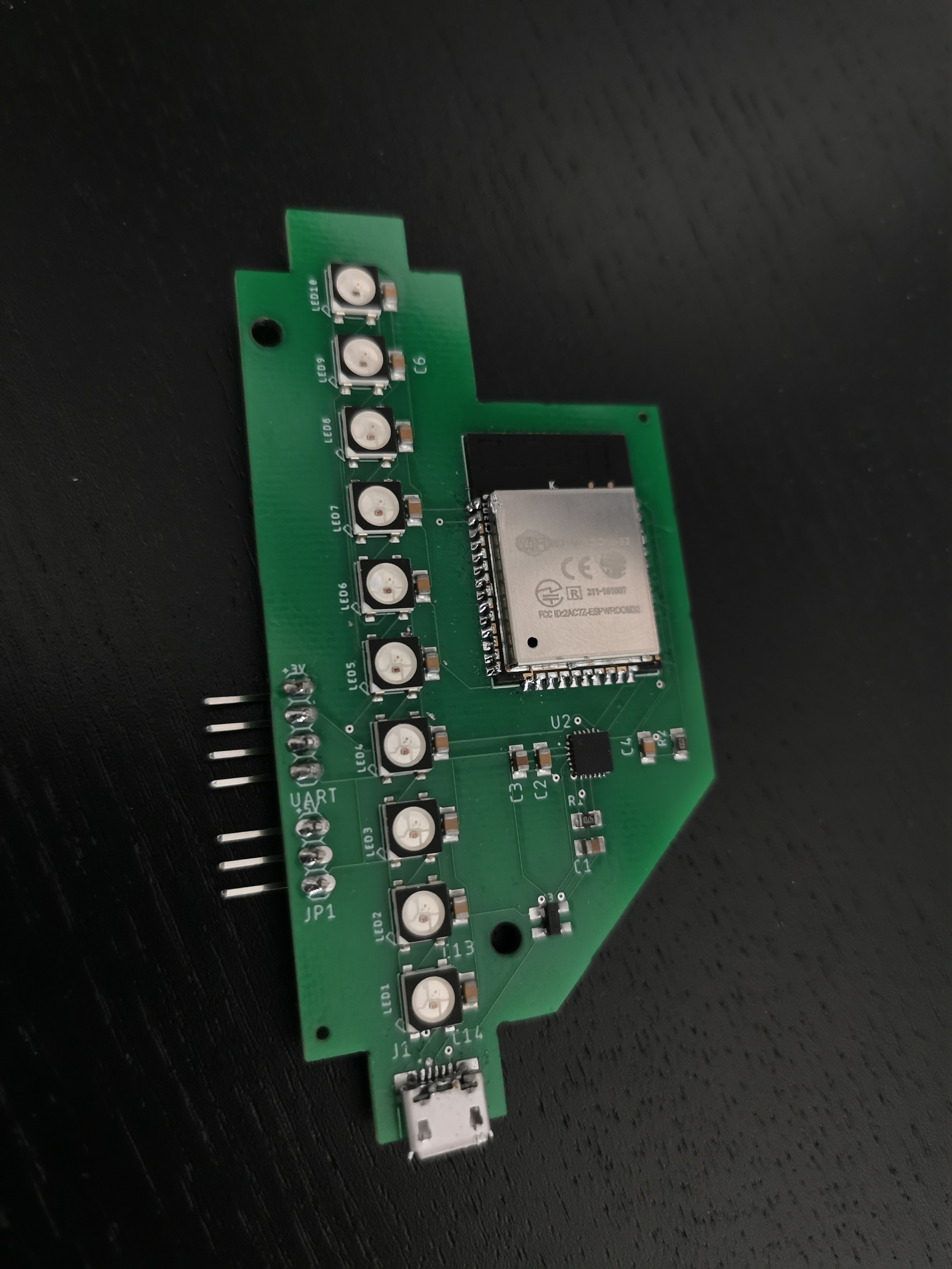
So I ordered another set of boards with a new revision: I replaced the 3535 version with the 5050 after triple checking that the pinout would be correct — while I did have a fixed part, I thought it would be better not to even suggest using a part that has a widespread broken pinout, and I did confirm I could fit the 5050 through the aperture by then. I also decided to move some components around to make the board a bit tighter and with a more recognizable shape.
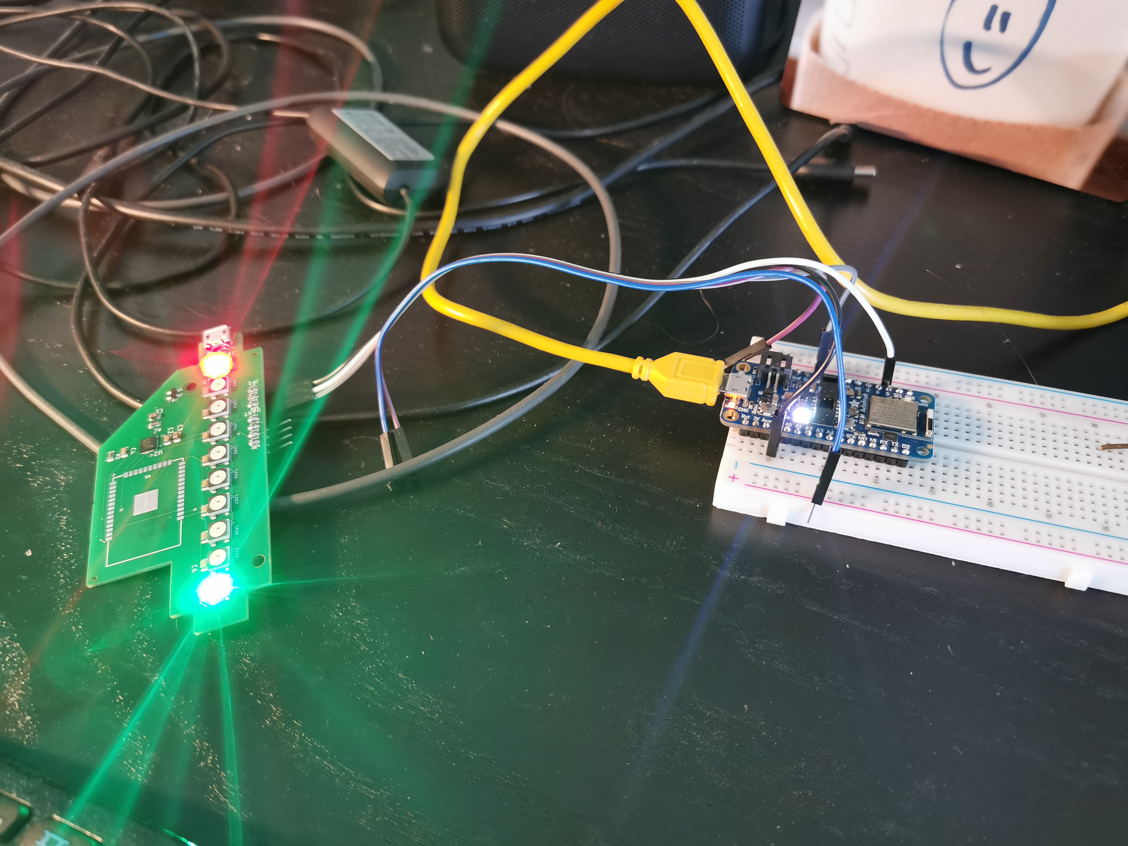
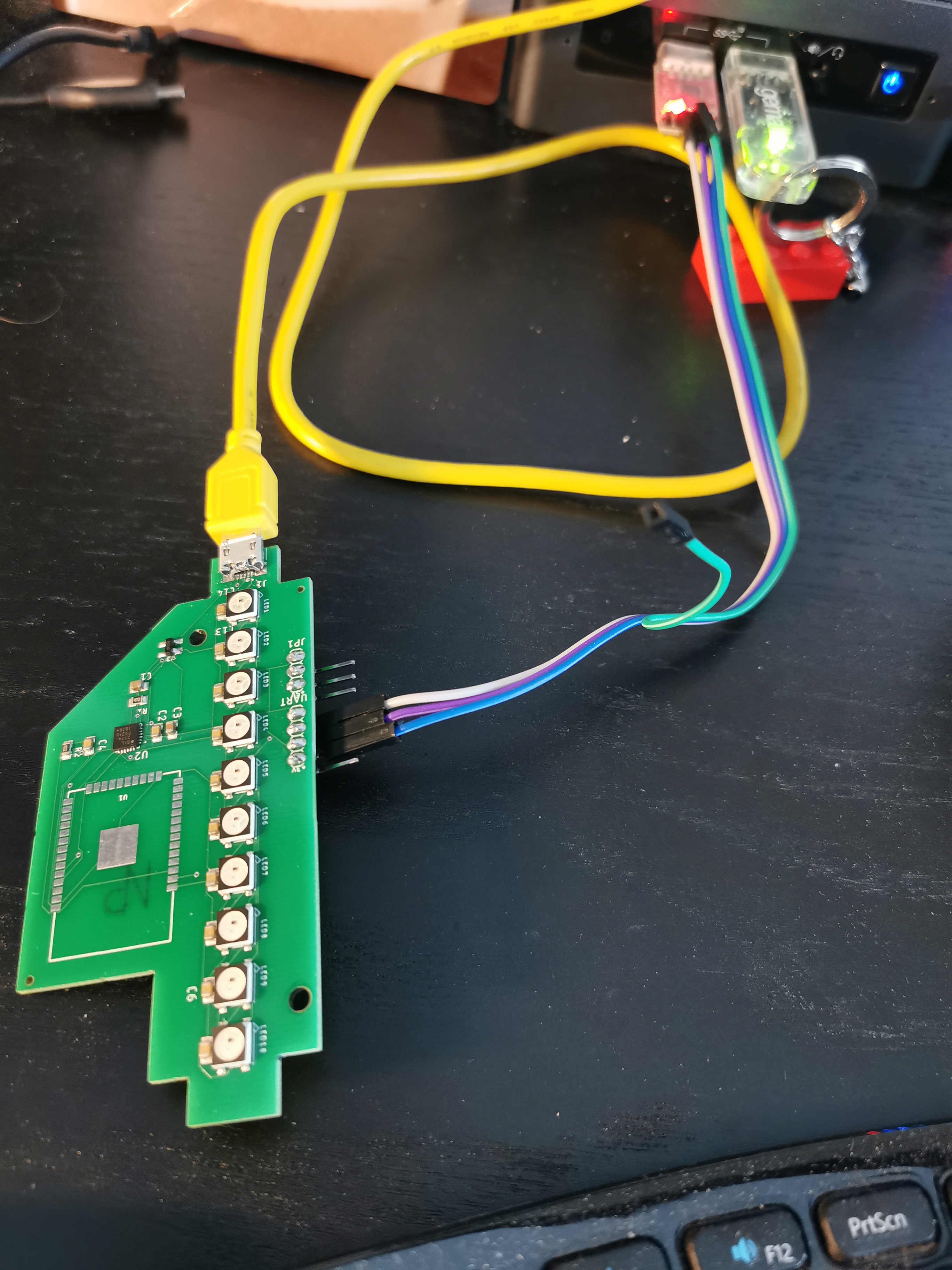
The boards arrived, without the ESP32-WROOM module on them — that’s because it’s not in the list of parts that JLCPCB can provide, despite it being sold by their “sister company” LCSC. That’s alright because I procured myself the modules separately on AliExpress (before I figured out that ordering from LCSC is actually cheaper). And I started the testing in increasing order of satisfaction: can the NeoPixel be addressed? Yes! Can the CP2104 enumerate? Yes! Does it transmit/receive over serial? Yes! Does esptool recognize the newly soldered ESP32? Yes! Does it fit properly in the base with the module on, and have space to connect the USB plug? Yes! Can I flash MicroPython on it? Well…
This is where things got annoying and took me a while to straighten out. I could flash MicroPython on the ESP32 module. The programming worked fine, and I could verify the content of the flash, but I never got the REPL prompt back over serial. What gives?
Turns out I only read part of the datasheet for the module, and not the Wiki: there’s something that is not quite obvious otherwise, and that is that GPIO0 and GPIO2 are special, and shouldn’t be used for I/O. Instead, the two of them are used to select boot mode, and enter flashing. Which is why GPIO0 is usually tied to a “BOOT” switch on the ESP32 breakout boards.
How does esptool handle these usually? By convention it expects the RTS and DTR line of the serial adapter to be connected respectively to EN (reset) and GPIO0 (boot), together with “additional circuitry” to avoid keeping the board in reset mode if hardware flow control is enabled. Of course I didn’t know this when I sent these to manufacture, and I still am not sure what that additional circuitry looks like (there’s some circuitry on SparkFun Thing Plus, but it’s not quite clear if it’s the same as Espressif is talking about).
I have seen a few schematics for breadboard-compatible modules for ESP32, but I have not really found a good “best practices to include an ESP32 module into your design”, despite looking around for a while. I really hope at least documenting what can go wrong will help someone else in the future.
Next Steps
I have a third revision design that should address the mistakes I made, although at the time of writing this blog post I still need to find the “additional circuitry”, which I might just forego and remind myself that hardware flow control with ESP32 is probably a bad idea anyway — since the lines are used for other purposes.
I also made sure this time to add reset and boot buttons, although that turned out to be a bit more of a headache just to make sure they would fit with the base. The main issue of using “classic” top-actuated buttons is that putting them on the top of the board makes it hard to find them once mounted, and putting them on the bottom risk to get pressed once I fit back the bottom of the base in. I opted for side-actuated buttons, so that they are reachable when the board is mounted in the base, and marked on the bottom of the board, the same way as the connectors are.
I’m also wondering if I should at least provide the ability to solder in the “touch button” that is already present on the base, and maybe add a socket for connecting the IR decode to reuse the remote controls that I have plenty of, now. But that might all be going for over-engineering, who knows!
Unfortunately, I don’t think I’ll be making an order of a new set of boards in the immediate future. I’ve already said this on Twitter, and it’ll deserve an eventual longer-form post, but it seems like we might be moving sooner, rather than later. And while JLCPCB and LCSC are very fast at shipping orders, I will be mostly trying not to make new orders of anything until we have a certainty of where we’ll be in a a few months. This is again a good time to put everything into a project box, and take it out when the situation feels a bit more stable.