In the previous part of the LG aircon reverse engineering, I gave the impression that the circuitry design was a problem mostly solved. After all, I found working LINbus transceivers, and I figured out a way to keep one of them “quiet” when not in use. And indeed, when I started drafting the post, it was supposed to be followed by a description of the protocol I identified, and should have been talking about how I wrote tools to simulate this protocol to test the implementation without actually touching the HVAC unit.
And that’s what I set out to do myself on a live stream, nearly two months ago now — the video says “Attempt 2” because on the first, short stream I ended up showing on stream my home wifi password and, even though it’s not likely that a bad actor would show up at my place to take over the wifi, it’s not good opsec, so I stopped the stream, rotated the password of all the devices at home, and came back to the stream.
So what happened? Well, while I was trying to figure out how to build an ESPHome custom component for the “climate” platform, but trying to send sequence of bytes through the serial port appeared to not work correctly: instead of being sent at the selected polling frequency, they would be “bunched up” together, sending three bytes instead of one, or twelve instead of six. It worked “fine” if I flushed the serial port, but the flush operation would then take longer than the time between the commands I wanted to send, so that didn’t sound like a good plan.
As you can imagine from the title, this particular problem only happened with the slow, 104 8n1 configuration that the LG aircon needs — it didn’t happen at all with higher baudrates such as 9600, which suggested the problem was related to the timing of the connection, which is not uncommon: a lot of UART implementations that include FIFOs tend to define some timing based on the timing of a “space” or of a full character.
What also suggested me that, is that someone, somewhere, was complaining that the ESP32 couldn’t do the slow speed that this aircon needs, and that they preferred using the ESP8266 because that one came with a software serial implementation. Unfortunately, I cannot find anymore where I read that, to link it there and to point out that the code for the ESP8266 software serial actually works without significant modifications on the ESP32 — it’s just that the lack of need for it means it’s not readily available.
So indeed, I managed to get the ESP8266 software serial to work… except for the fact that it was not quite reliable. At 104 bps (which is the speed the aircon protocol needs) sending a six bytes sequence (which is the size of an aircon packet) takes about half a second — add another half second for the response (which is also six bytes), and you have a recipe for a disaster: one second every two seconds (which is the frequency of command exchange between panel and HVAC) would be spent just on serial communication — anything else happening during those time and messing up the timing meant bad communication.
Another nearly-software-based alternative I attempted, and also kind-of worked, was using the RMT peripheral. This is the remote control peripheral included in ESP32 — and the reason why Circuit Python made it harder to send pulse trains on FeatherS2: it’s no longer just implemented in software, but it relies on hardware buffers to allow sending and receiving pulse trains. It’s awesome to offload that, but it also comes with limitations. In particular, while I did manage to implement a 104 bps serial transmission through this interface, it would only allow me one serial pair rather than two, severely limiting what I could be doing with the aircon board.
Content Warning: though I’m personally aiming at following more modern conventions, the terminology in use by datasheet and other content that I’m about to link to still use older, less inclusive terminology.
UART — But Discretely
So instead, I used my overcomplication skill to come up with an alternative: discrete UARTs! You see, back in the days when personal computers came with serial ports, and before chipsets started having everything into a single physical chip, and even before most of the functionality of basic peripherals was merged into a Super I/O chip, we had multiple competing discrete UART chips available. The most common one being the 16550, at least for my personal experience. These are still available, and you can indeed still use the 16550, although to do so you need to use a lot of I/O lines, as 16550 and compatible have usually a parallel I/O interface, which is suitable for ISA bus connection, but not so suitable for a microcontroller even when it’s quite generous with its GPIO lines.
As an alternative, I started looking into using a SC16IS741A, which is a I²C (and SPI) chip. Instead of using a lot of separate I/O lines for sending commands and data to it, you send it with the usual two wire interface, and it internally decodes it into whatever format it needs. You may wonder what the difference is, between using the actual UART and sending it over to an I²C hardware UART — the answer is a bit complicated to explain theoretically, but I think a visualization of it will go a long way to explain:
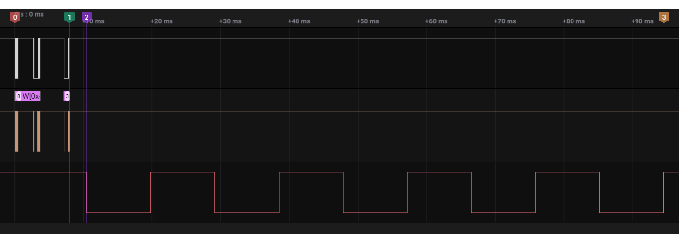
What you see here is a screenshot from the Saleae Logic software capturing three I/O lines: the I²C bus (SCL above, SDA below), and the TX line of the discrete UART. This is a very much not optimized transaction that shows the sending of one byte at the 104 bps configuration that my aircon control needs. It’s one order of magnitude slower to send the byte than to set up the UART to send the message and send it, and this is with a relatively slow bus as I²C is. And it doesn’t scale linearly, even.
Basically, the discrete UART allows offloading the whole process of keeping up with the timing, and it does so in a very efficient way. Receiving is even more interesting, because it does not require the microcontroller to pay attention to the received bytes until it’s ready to process them, and maintain them in the FIFO in the meantime. But this kind of features already exist in most microcontrollers (often referred to “hardware UART”), and when they work, that’s awesome… but clearly sometimes they don’t quite work.
This particular device would be useful on boards based around the older ESP8266 micro, as that only has a single hardware UART, and is used for the logging. With one (or more) of this or similar chips you would be able to control a much wider number of serial-controlled devices, and that makes them valuable.
Unfortunately, ESPHome does not really have a way to provide an uart bus outside of the core platform, at least right now. If I did end up working more down this particular route, I would probably have paid more attention to integrate it — it’s not hard to provide the same interface so that it would be a drop-in replacement, but it does require some reshuffling of the core hierarchy so I don’t think I can pull that out just yet.
Writing a Device Driver, a Component, a Library
In either case, whether you want to integrate this directly in ESPHome, or use it from another software stack, you need to implement its own command set. This is what you usually refer to as a “device driver” for operating systems such as Linux and Windows, as it provides access to the underlying device with some standard interface. And indeed, the Linux kernel has a driver for a set of related of NXP UART peripherals: sc16is7xx.
Now, while the NXP-provided datasheet has all the information needed to program for this chip, having the source reference on Linux made things significantly easier, particularly because unless you know what to look for, you most likely will misread the datasheet. I have some (though not much) experience with I²C devices, but there were a few things that ended up confusing me enough that I wasted hours down the wrong route.
The first problem was figuring out the addressing convention. I²C addresses should, by convention be 7 bit. While the protocol sends a whole byte for addressing, it uses the last bit in it to specify whether you’re issuing a read or a write. But despite this being the common convention, and the one that ESPHome, CircuitPython, and just about anything else expects you to use, some datasheet do not follow that, and provide the full 8 bit “address”. You can see more details on that on the Total Phase website, which was instrumental for me to get to the bottom of why things kept disagreeing with what I was writing.
Once the peripheral was addressed, the question to answer was about the registers addresses. In my first attempt at configuring the chip I was falling short. A quick look through the Linux sources told me that I was missing a left shift of the register address… which made me go “Huh?” for a while. Indeed, the datasheet provides explicit tables explaining the register addressing: registers have a 4-bit address, but are set in the 3:6 bits of a byte, with bit 7 (MSB) being used in SPI only to select between reading and writing to the register. Of the remaining three bits, two are used to select between channels — because some of the matching chips by NXP include more than one UART on board, though unfortunately I couldn’t find one that I could easily work with on a breadboard that did. The last one (LSB)… is not used. It’s always off and reserved. But more interestingly, the Linux driver only shifts the address by two, not by three like I had to. So I’m wondering if this does mean that this chip is only mostly compatible with the ones I was looking.
So after one full day of figuring out how to properly run my component over ESPHome, I decided I needed something for prototyping this I²C faster.
Enter Circuit Python
By now you probably know that I do like Circuit Python. And as it turns out, I already have written some code for I²C in Circuit Python when I extend the MCP230xx library to include the older ’16 model. So it didn’t feel too odd to go ahead and use a Trinket M0 with Circuit Python to play around with the UART.
The choice of the Trinket M0 over the more capable Feathers was not random: while the Trinket has a physical UART and the pins to use it, it’s also a very tiny device. The fact that you can use multiple physical UARTs through the I²C bus allows a significant expansion of the I/O abilities of that class of microcontrollers.
At the end, I not only ended up writing a CircuitPython compatible library that allowed me to use the UART, but also re-writing it to leverage the Adafruit_CircuitPython_Register library, making it significantly easier to add support for more features.
The library supports an interface that is nearly identical to the one provided by the built-in serial, although I don’t think theré sa way to make sure it really is, because similarly to ESPHome it doesn’t look like Circuit Python ever consider the need to support UARTs that are not part of the original hardware design, understandably so, as these discrete UARTs are still fairly uncommon.
But I went one step further: when I read the datasheet the first time I wasn’t sure just how strong the suggestion for 1.8432 MHz crystals was, for the divisor. Turns out it’s not strong at all, so the whole amount of crystals I bought at that frequency are not particularly helpful. Worse yet, it turns out I don’t need any clock, because even the Trinket M0 is able to create a 50% duty cycle PWM output at a frequency that is high enough to use as driving clock for the UART.
That means that I can fit, in a half sized breadboard, the whole circuitry I need, including only two passives (the pull-up resistors on the SCL/SDA lines), providing the clock as a PWM output from the Trinket while also piggybacking its reset line. This was a surprisingly good setup, and would actually allow me to control the two sides of my aircon (panel and hvac) if I was still going with the discrete UART idea.
But it turns out I really don’t need any of that: ESP32’s UARTs worked out just fine at the end — at least in the most recent firmware as uploaded by ESPHome, so I decided to set aside again the UARTs and try instead to control the aircon at least with an USB-to-UART adapter. But that’s a story for another post.
Bonus Chapter: Dual-UART chips
As I said earlier, there are some options out there for multiple UART chips that would be interesting to use for cases like mine, in which I need two independent, yet identically configured UARTs. Dual UART chips are not uncommon, but I²C controlled ones are.
If you look around for I²C Dual-UART options, you most ilkely will end up on the DFRobot DFR0627 which is an “IIC to Dual UART Module” — IIC being the name you’ll find used on Chinese products to refer to I²C (it’s like TF card instead of SD card, don’t ask me.)
So why did I not even consider this particular option? Well, the first issue is that this is a full module, that uses the Gravity connector (which is similar to, but as far as I know not compatible with, the Stemma QT connector that Adafruit uses), the second issue is that there’s no documentation to go with how to use it.
Since I want to, at the end of the whole process, have a printed board I can just hang on the wall (possibly with a 3D Printed case, but that’s further along the way), I need to be able to get the components I want in retail-enough options that I can buy them and solder them in myself. I also need to be able to control those components with arbitrary software.
The DFRobot modules tend to have Arduino components, which you may still be able to use for ESPHome, but you wouldn’t be able to use with Circuit python during the more iterative side of the project. Since these components are open source you could go ahead and reverse engineer it from those, but it would be much easier to develop for something that has a datasheet and some documentation.
Indeed, the DFRobot website does not even tell you what chip is on the module. though if you look around in the forums you can find a reference to WEIKAI WK2132-ISSG, which is available through LCSC and comes with a datasheet. In Chinese.
If you just look at the pictures, you can at least confirm that this device is similar in functionality to what the NXP part I’ve been working with provides, except for the fact that it does not have the full RS-232 style CTS/RTS lines. So it really would be an interesting part if I ever decided to go back to the idea of using discrete UARTs, but it would require at the very least for me to get one of my Chinese-reading friends to translate enough of this 28 pages datasheet to be able to tell what to do. That is unlikely.