You may remember that two months ago I declared my art project completed, and posted pictures of it. I have asid back then that it wasn’t quite all done and dusted, because I have been waiting for PCBs to arrive from PCBway, an online PCB ordering service that has been heavily advertising on YouTube makers’ videos for the past year or so. I ordered those back in April and, now that it’s July, they still haven’t turned up! I decided instead to follow again the advice of bigclive, and tried JLCPCB instead, which turned out to be a very good idea: ordered on Sunday, the boards arrived on Friday!
So on Friday I set myself to spend some of the time listening to training talks, and solder on the boards, which turned out to be a bit less practical than I intended — I might try again to solder microUSB connectors, but then I’ll follow Richard’s advice and try without the shielding in the back. After some screwups, I managed to get working boards, programmed a new STC89, and went on to connect it to the LEGO set — and it all turned up at once, which it wasn’t meant to!
After trying a few combinations of different Darlington arrays, and flashing a new build of the firmware, I ended up figuring that all the micros I flasked anew were completely stuck, with all the I/O ports staying at 5V with an occasional momentary pull down. At first I thought I screwed up the R/C network for the reset line, but no, I managed to check it with the Saleae Logic Pro and the reset line behaves exactly as it should have. I also popped in the original STC I used, before the ones I ordered on AliExpress arrived from China. And it worked fine, if a bit misconfigured (the new firmware has a few fixes). I also tried it and one of the “pristine” ones on the programmer, and they all work fine, but anything I program anew fails the same way.
It’s not a firmware problem either: I tried going back in time and build even the first draft version; I tried demos written by someone else; I tried four different versions of SDCC — all to no avail. Nothing changed in stcgal so it doesn’t sound like it’s a problem there… I’m at a complete loss of what’s going on there. I honestly felt desperate about that, because it worked perfectly fine two months ago, and now it suddenly stopped.
So instead, I spent Saturday working on my plan B: using CircuitPython for the main scenes logic, with an Adafruit board — in particular I decided to start working with the Feather M0, but I’m targeting the Trinket M0, which is cheaper, smaller, and still plenty powerful for what I need. This was also fun because, since I designed the actuator board to be separate from the MCU and in particular to be possible to plug it into a breadboard, which means that half of the design was already known working and didn’t need redesign.
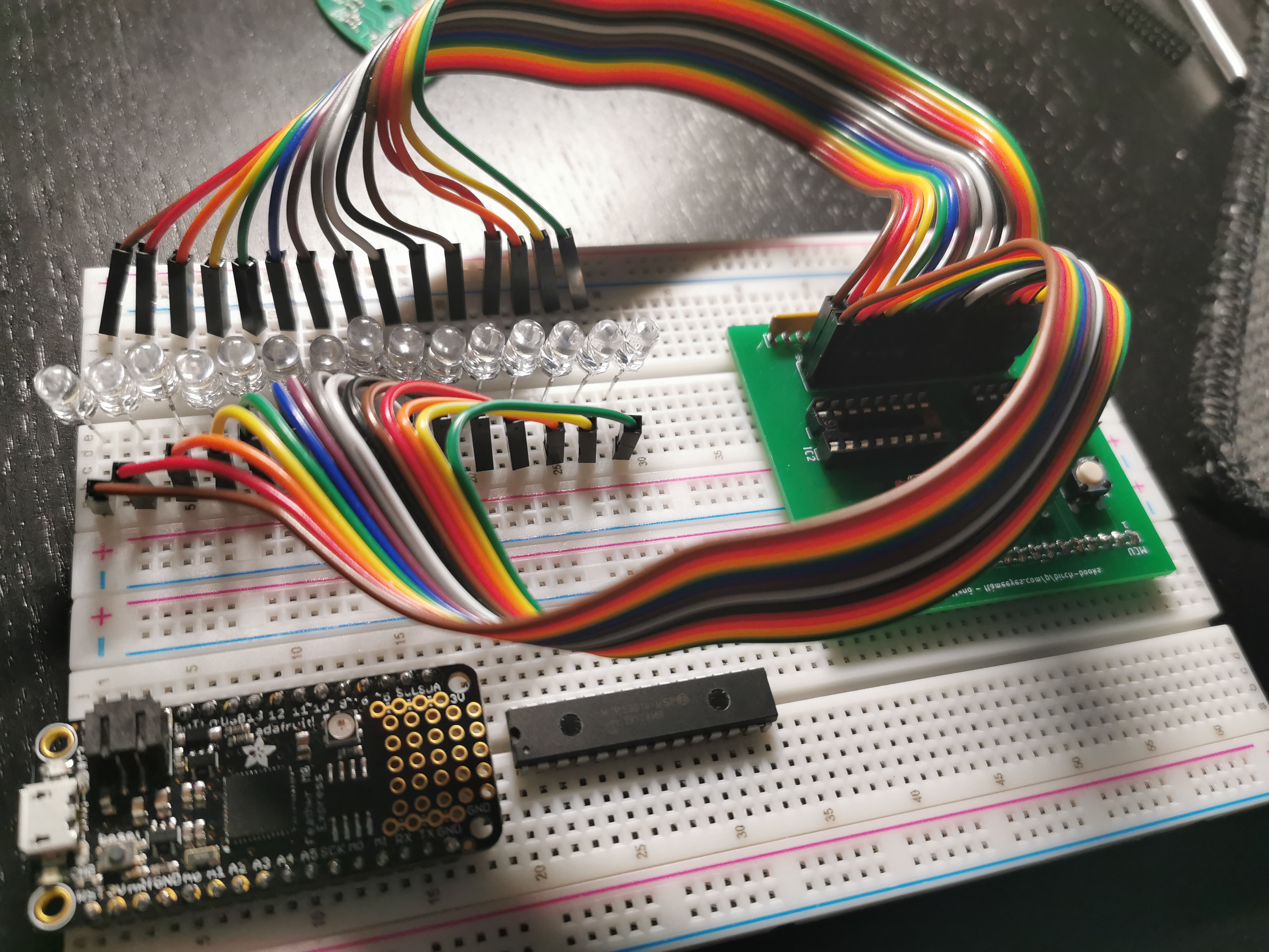
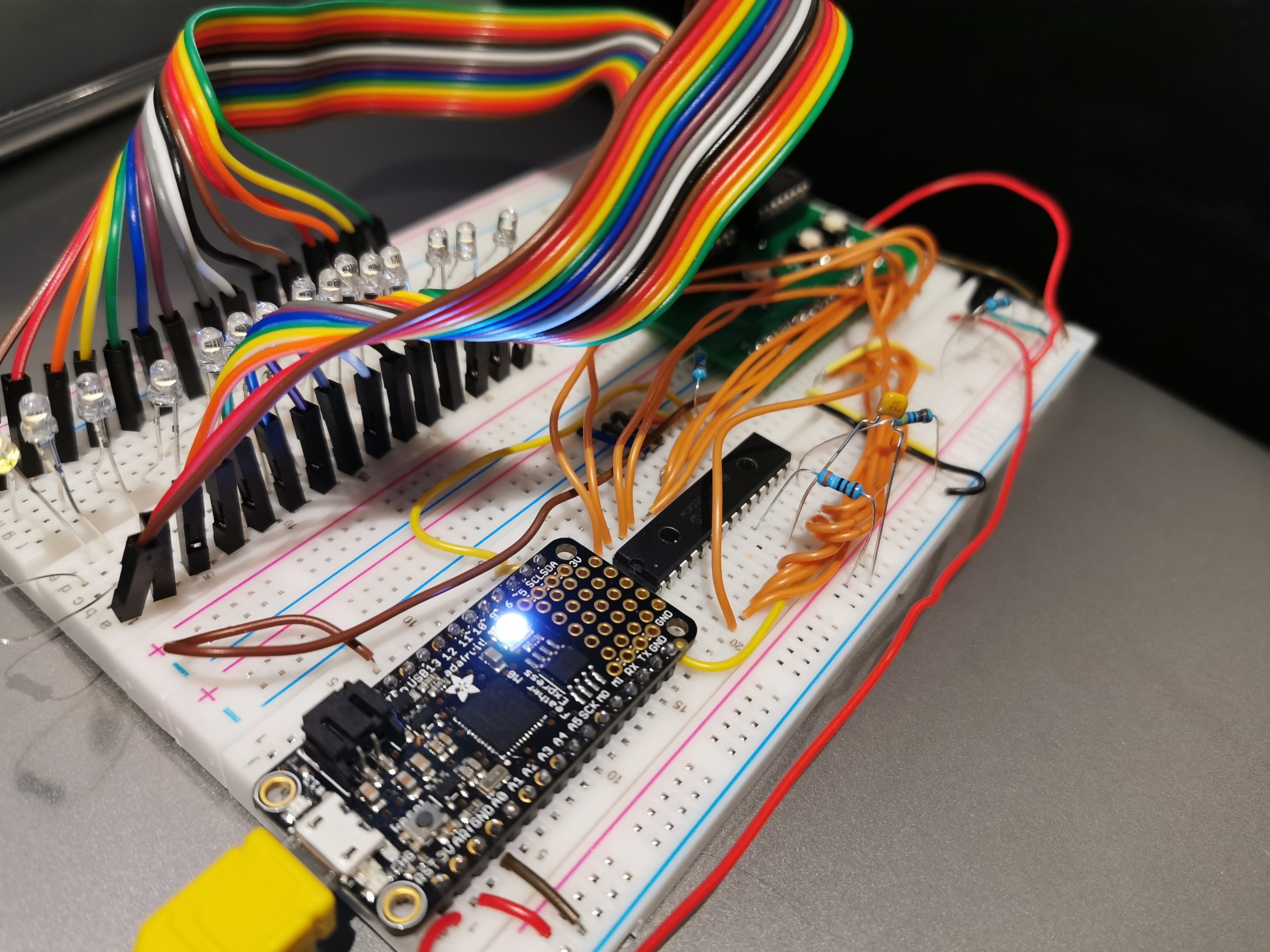
Unfortunately what I didn’t think of was to produce a test board that would just plug into the pins on the actuator board to test it, without connecting it to the bookstore… so I ended up having to manually wire a lot of LEDs on the breadboard to turn them on. I’m going to use this as a visible example of why you should always build a fake of your service if you’re writing a client, to run integration testing with! I am addressing this by ordering an explicit testing board to connect on top of the actuator, so that I can just use it. Also fun fact: it looks like the LEDs that I have used in this pictures are… more sensible than the other ones, and Sparky the Blue Smoke Monster came to visit me again when I gave it a straight 5V.
There’s more jankiness going around with this board, though. When I was looking at expanding the I/O capabilities of the Feather, I ended up buying a few MCP23016 expanders. These are I²C chips that provide access to 16 input or output lines while only requiring two wires on the MCU. I can’t for the life of me remember or figure out why I went with this particular model, that currently sports a «Not Recommended for new designs.» warning on the top of the Microchip product page. I might as well have mistyped the MCP23017, which is the modern version of the same chip.
Beside not being (at all) pin compatible, the documentation on Adafruit’s website is designed for the later (’17) variant, and indeed the older (’16) version is not currently supported by CircuitPython (although I’m addressing this). It doesn’t stop there: 16 requires an additional R/C network, which turned out to be very unreliable: it ended up working better with a single resistor on the CLK line, and I’m not at all sure on why. So in general, the difference between MCP23016 and MCP23017 is that the latter is much nicer to use. Since I do have a few 16, and the components needed for the RC network, I’ve started writing the CircuitPython code based on that first, but also designed a separate board to fit the ’17, using a non-default address, so that I can distinguish between the two at startup.
Part of the reason for that is also that the ’16 is very finnicky, and when it receives a command it doesn’t entirely like, it decides to simply crash, and requires a full power cycle (not just a reset), which isn’t very good.

There’s another jankiness that you can possibly spot on the right side of the board: why is there a transistor, in this fairly minimalistic design? I mean okay, the pull-up resistors for I²C lines, and the RC network already ruined the idea of having the daughterboard and the expander only. But a transistor? Well, it turns out when I designed the actuator board I made a silly mistake: I didn’t consider that reset lines (RST) are not always active high (as they are on the 8051), but are sometimes actually ¬RST — and as you can imagine now, both the Feathers and the Trinket M0 are indeed active low.
And since pushing the Reset button is bridging the RST line of the actuator board to VIO (hey, at least I did realise that if I went to a different platform I would need a different “logic high”!), it wouldn’t work at all. Instead, it now activates the transistor, so that it bridges the RST line to ground. Basically, a NOT gate implemented with a single transistor — which I might have remembered thanks to Richard Feyman Lectures on Computation, which is a book I actually would recommend for those interested.
And if you’re wondering why the I/O lines are all orange, I checked which equipment wire roll I had the most of, turned out to be orange.
Also, a word of advise that I found out by complete random chance as well: the default for “quote dimensions” in Eagle is to put them in as traces at the top of the board! When I sent the generated gerber files to JLCPCB this time, they noted some dead shorts and asked me to confirm if that was intentional — so kudos to them for noticing. They allowed me to upload new, fixed gerber files after that.