I started talking about my quarantine (or, well, lockdown) art project at the end of March, with a plan. I did manage to (mostly) complete it by the end of April, while the lockdown (and my sabbatical) are still in full swing.
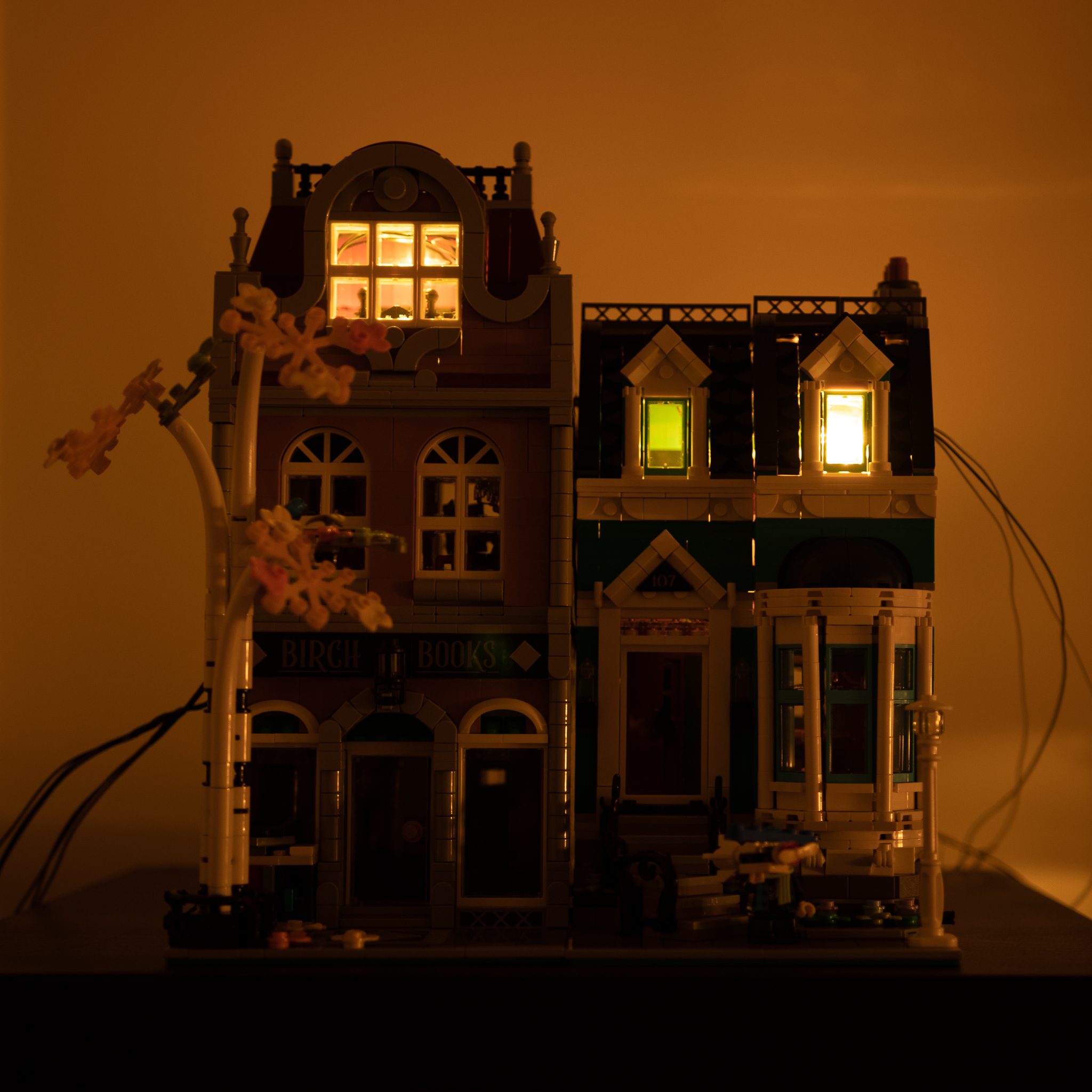
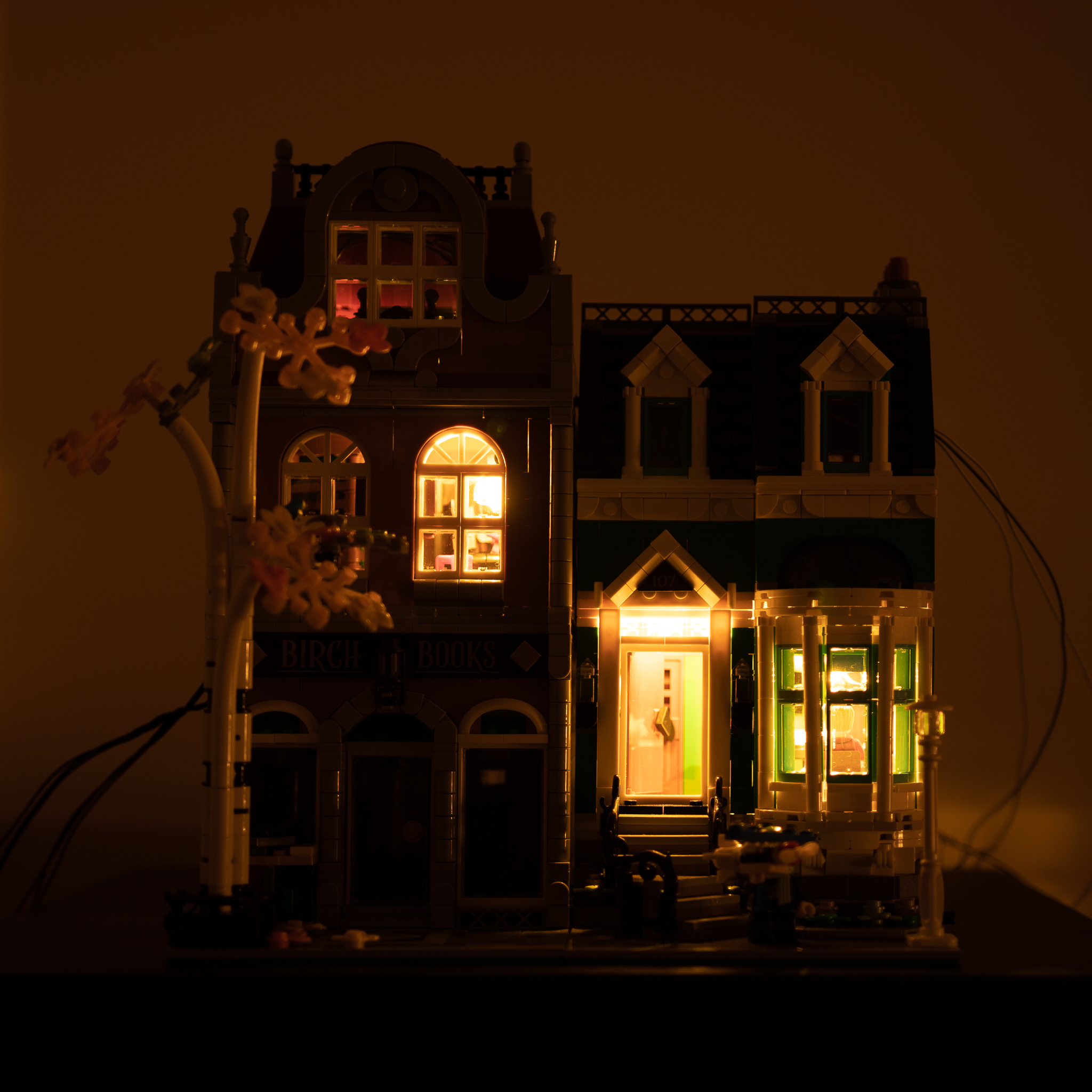
I have shared some work in progress pictures over on Twitter, including a 2-minutes video (shot on my phone by hand, so not very high-quality) showing the full set of scenes (before the latest “firmware revision”). As you can see from all those pictures, the cables are still pretty much in the way and very visible. That’s not something I have addressed yet, but I’m waiting for the PCBs to arrive before doing that.
At the end, the result is that throughout the building there are 12 bright white LEDs, connected via Dupont connectors to a harness that then goes into the breadboard — that’s so that the harness can disappear the moment I have the PCBs.
For the PCBs, I think I made a rookie mistake. I ordered them from PCBWay, as I heard good about them on the tubes, and they seemed to have a good price point even for assembly of the SMD versions. That was not the mistake. The mistake was to send a single order with both the SMT and the through-hole PCBs, to save on shipping. I’m now having to wait until the end of this month to receive the boards, and hope I didn’t make any more mistakes on them. Edit 2020-07-01: nearly three months later, the PCBs have not turned up. I ended up ordering a new batch from JLCPCB (not an affiliate link) that arrived within a week. Beware of YouTubers being paid for it.
I’m also sure that there will be changes I’ll need to make. These are literally the first printed circuit boards that I design, and beside obvious stylistic mistakes (such as not marking the value of components), I’m sure there’s more mistakes than that. So I expect I’ll have to update the designs later on. Hopefully it won’t get a mess of bodge wires when I try to use it properly.
I have to figure out how to fit all of this into a box, eventually. Probably a Lego box of some kind. And I’ll probably have to make sure that the USB plug is fit properly. Soldering a microUSB connector on a PCB is… not easy and not something I’m looking forward to. That’s why I added a 5-pin header on the design, so I can use one of the cheap breakout boards you can find all over on AliExpress or eBay.
The 8051 based firmware is available on the same GitHub repository, and it includes a full 16-scenes (although not unique scene) schedule that now runs in about one minute.
I also changed the “boot test” mode in the second “firmware revision”: instead of trying to turn on each LED one by one, it turns on each room one by one. The reason why I did that, is that I have hooked up multiple Darlington gates through a joint to provide more current for a couple of rooms that have three LEDs on the same room. This might have been a bit of a mistake and I should probably rewire those rooms to just use multiple LEDs, but that’s not going to happen any day now.
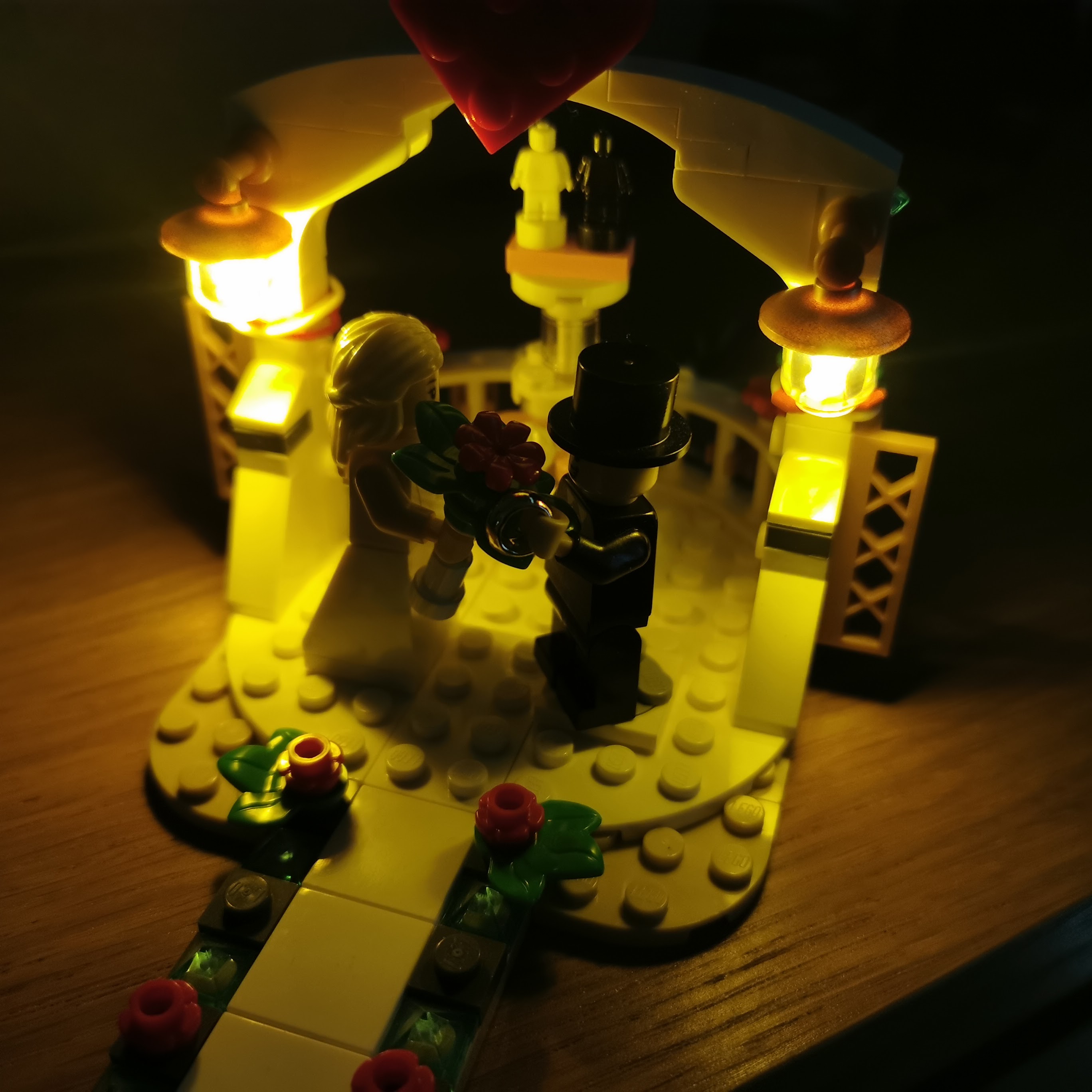
Also, with a bit of a hindsight, I should probably have just left the current-limiting resistors off the actuator board altogether. While the resistor networks are great to simplify the design, I could have just as easily soldered the resistors inline on the cable and wrapped them with heatshrink. I know because I did exactly that on another Lego set, when I realised that powering it directly from a 5V supply was significantly overheating one of the two LEDs.
This is, by the way, another “trick” learnt while watching bigclive on YouTube. Probably not something that would be worth a complete video on, and maybe something that felt fairly natural and not required to explain to him but… something I’m very happy to have learnt. Which is why I love rambling on about small choices in my thought process, as it’s very possible that something that is natural and obvious to me, is not for someone else reading me. And why I do welcome comments asking for clarification on points I may be glossing over.
Also, both my wife and my mother have been pushing me to figure out what the next Lego model I will be adding lights to is going to be. I don’t honestly know, right now. But I guess the lessons learnt with this model should allow me to step up to something a bit more complicated next time. For sure, it would be a cheaper and easier job, since I procured a lot of tools for it anyway.
I think that the things I will consider changing for next time are not just the place the current-limiting resistors are connected (which I can probably retro-fit on the current PCBs), but also the type of wiring I use for the LEDs. I used equipment wire for this build, and it turns out to be fairly stiff and unwieldy. If I were to re-do this, or do it to another model, I would probably use the equipment wire only within the rooms themselves (that way I can push it out of the way), and then solder it just outside the model with a stranded, softer wire.
I think this will probably be the end of the regularly scheduled updates on my art project, at least until the PCBs arrive. I did intend to draw some documentation with a tool like Fritzing, which is used by Adafruit for their documentation, but I’m having quite a few headaches even figuring out how to set it up. None of the components I need are part of their parts libraries, and the documentation is out of date regarding the parts editor, so don’t hold your breath.