Now that I’m free from my previous employer’s open source releasing processes, I’ve finally decided to put ideas to the computer and figure out how to actually build the controller board, and its firmware. It does help that I’m still missing the crimping tool to add connectors to the LEDs so I can test them, and that I had to think things through a bit more before ordering chips.
First, I needed to figure out what interactions I would get. As I said in the previous post, the plan is to have a single pin pair per driven LED, even when LEDs would always switched on and off together. It just makes the layout much cleaner, particularly as then there’s no need to encode knowledge of the final layout into the electronics. The final count of LEDs I’m looking at is 13, and as I’m going to use two Darlington arrays (ULN2003), I rounded that up to 14. And just to have some extra, I decided to add a straight +5V pin on the final connector, just in case I decide to do something else with it later.
As the target micro (STC89C32/AT89S52 and similar chips) comes with four 8-bit ports, this means that using two ports only, I can add an additional two inputs, which fits with my needs: a button to toggle turning on all the LEDs at once (useful to take detailed photos), and one to “fast forward” — so that instead of waiting for X minutes to change scene, it would wait X/Y (numbers and timing still to be defined).
Choosing the ports turned out to be a bit more complicated than I would have expected. The reason for that is that I also wanted to keep track of how to flash the micros. While I do have a “programmer” board (which is actually an overall test board) for the STC micros, I wasn’t sure how it would look like once completed, and didn’t really feel like unsocketing the chip every time I wanted to make a change.
According to the two datasheets (STC89Cxx, AT89S52), both chips include “In-System Programming”, but they do it quite differently. The STC uses the UART (serial) line that is standard on the 8051 chips and forms part of P3. This is what stcgal uses to program the chips, and I have tested that it works with any serial adapter connected to the right pins. The Microchip version uses I²C instead, using the three upper lines of P1.
This means that, to keep the board as simple as I can, without using the same pin for two functions, I’m better off using the P0 and P2 ports — these are used for address and data busses, when using external memory with the 8051, but that’s not something I need, so they are easily dedicated to drive the I/O of the controller board. Annoyingly, in the 40-DIP version of the 8051 and compatible chips, P0 and P2 are, yes, on the same side of the chip, but also “bookended”: pin 32 is P0.7 (highest bit of P0), and pin 28 is P2.7, which means that to keep the outputs linear you either need to reverse them in software, or in hardware. I went for hardware, since EAGLE’s Autorouter can do that faster than I can do it in software.
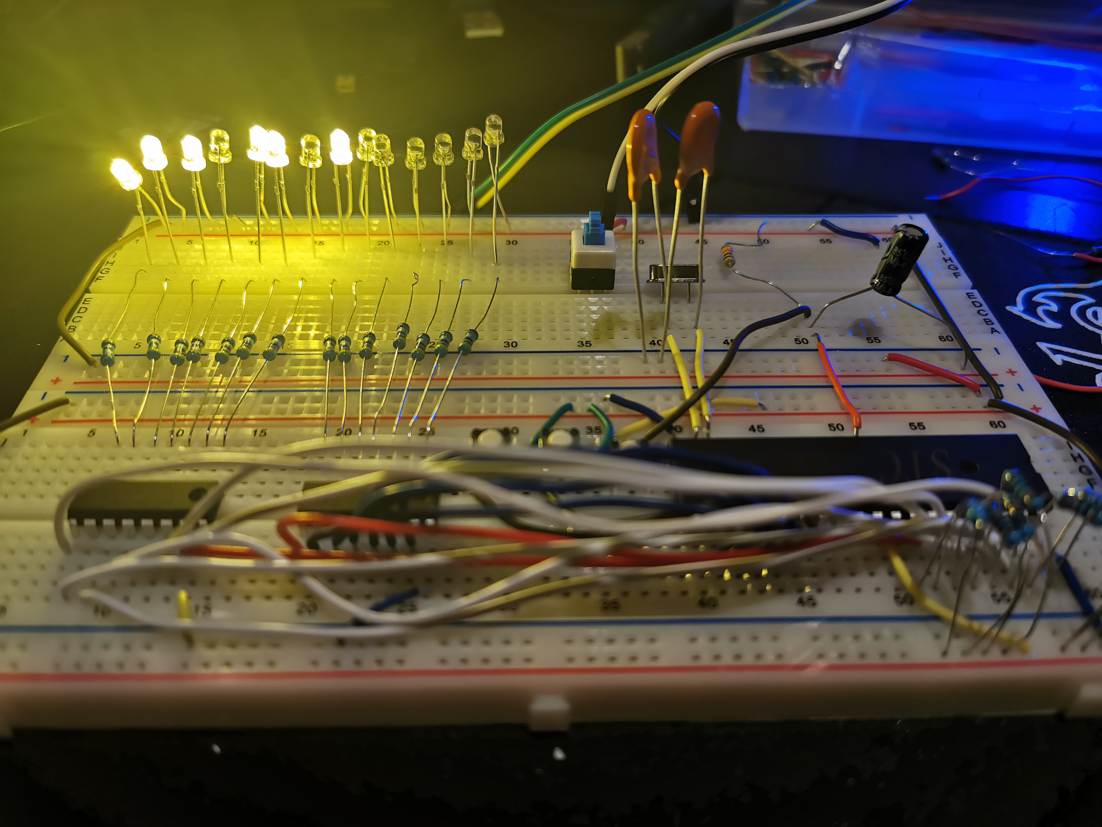
I also got bitten by a quirk of the 8051: P0 is the only port that needs pull-up resistors! The I/O lines on P0 are tristate (On, Off, NC) and floating by default. I didn’t notice that before because obviously the devboard I’ve been using has them already. Thankfully, before ordering anything I wanted to try the whole set of components on a breadboard (pictured right), and found that out pretty quickly. There was a hint of this in the heart-shaped circuit I keep going back to: the LEDs on that board are all wired with common-anode, which effectively turn their resistor into the pull-up. I totally missed it, but I was in time to fix the board, and to order some resistor networks so that I don’t have to end up soldering 16 extra legs, but just 9.
Now as I was preparing this I also figured out that, if I do provide the ISP connectors for both AT and STC chips on the board itself (and at least it appears that the STC programming works the same way for other chips, including the STC12C5A60S2), I don’t need to limit myself to DIP chips — I can use a socket PLCC, or a surface-mount LQFP, and just program it on the board. So I tried to figure out how different would an SMD board would be — and realised that there’s effectively two parts to the board as I had been picturing it it in my mind: the controller, with the microUSB plug, the micro and its paraphernalia (crystal, RC net, etc.), and the ISP headers — and the actuator, which receive the signals to turn on and off the LEDs, and sends the button presses, and then translate those in the actual powering up via the Darlington arrays.
So what I ended up doing was designing two separate boards, connected with a straight 1×20 pin header, carrying the 16 I/O signals, and a few extras. In addition to the +5V and the ground, it carries an RST signal (which can be either consider the 17th I/O, or just wired straight into the micro’s reset line, like I did), allowing the whole board to be reset, without having to powercycle it, and it also carries a Vcc line.
Why the extra Vcc line? Well, as I’ll explain in a post next week (hopefully with more positive information rather than just the rant it would be now), I’ve been considering alternative MCUs as well, for the controller. Not least because the 8051 is a very strange thing to program. One of the chips I was considering was the ESP32, which is fairly cheap and easy to find in the market, since nearly anything “IoT” is using it, as it supports WiFi and Bluetooth out of the box, and can be used as a “co processor” as well. It turns out to have enough GPIO pins to not require a multiplexer, but it also uses 3.3V CMOS levels rather than the 5V TTL levels that I’ve been thinking in, for the 8051 version. And for that reason, I need to distinguish, in the actuation board, the supply used to power the LEDs on, and the logical High for the inputs.
This exercise was useful to also figure out that I was completely wrong in the board files I pushed originally! I had not paid enough attention to the ULN2003, and assumed it was a standard PNP transistor, but Darlingon arrays are NPN transistors. So LEDs will have to share the supply cable, and use multiple ground connections going through the Darlington. Again, this would lead to a common-anode design.
So now the boards are in the repository, even though they are probably terrible. There’s some basic documentation as well explaining the pin connections. There are two versions of the actuator board, one using SMD components and one using through-hole (PTH) — the reason is that I’m likely going to buy the prints from PCBWay, and they can manufacture the SMD version fully — but it will take 40 to 50 days. So I’m planning on having that manufactured for later, but in the meantime I wanted something I could prototype on — so the through-hole came later, as you can tell by the fact I realised I could put resistor networks between supply and anode, rather than between cathode and Darlington.
Edit 2020-07-01: nearly three months later, the PCBs have not turned up. I ended up ordering a new batch from JLCPCB (not an affiliate link) that arrived within a week. Beware of YouTubers being paid for it.