I already introduced my quarantine art project, and as I promised here comes the second blog post on the topic, just to keep my own running notes around.
First of all, I decided to at least (partially) follow the advice from Adam Savage in his biography, about making lists and planning carefully. Indeed, I decided to write on paper as much running notes as I could and I could make sense, particularly since, as I said in the previous post, I’m not really at ease with electronics and I’m just lost at most of the things that are needed for this project, truth be told. So shout out to my friend Srdjan for helping me keep an eye on the things that are required!
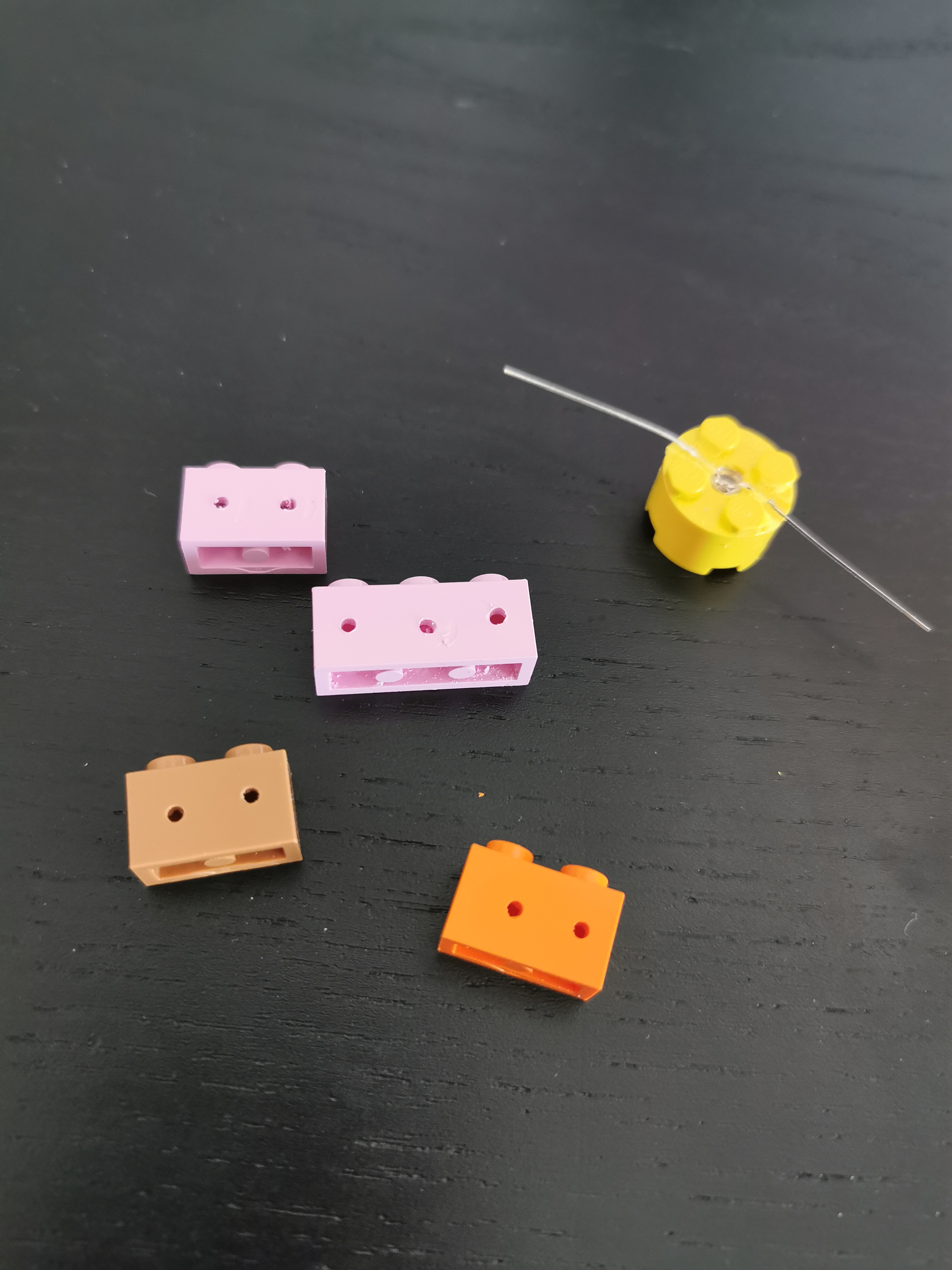
One of the things I clearly needed to solve was the access point for the wires themselves. The cable I have at home (without me going and buying more) is “equipment wire” (I got this a couple of years back because it’s single-core and made my protyping on the breadboard easier), and it is 0.6mm in diameter. I’m sure I can probably look for thinner wire, like wire-wrapping wire, and it’ll be perfectly fine to run 5V/50mA. But unless I deem it’s going to be impossible to keep hidden the wire I already have, I don’t think I’ll be buying more wire just yet.
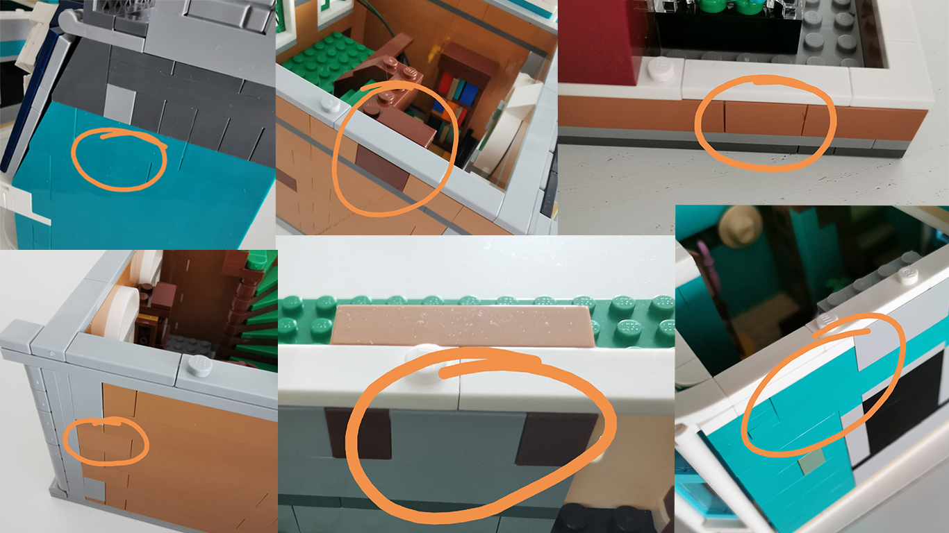
Because of the nature of the model, the easiest way to modify the set without it being too noticeable it’s on the sides — Birch Books is designed to fit together with other Creator kits, and can be connected together through the base. Indeed, the kit itself is composed of two buildings that are connected at the base, and otherwise perfectly independent. This would be a problem if I decided to buy more sets of Creators, but then again, let’s cross this when it comes.
I also want to make sure that I don’t have to modify the pieces coming from the original kit. While I’m sure all of those are replaceable, it’s easier to keep them aside, and modify other pieces. I bought myself a box of assorted bricks, and I was lucky to find a few pieces that were already the right colour and shape for what I need.
I have then started dividing the set into rooms, and then for each rooms figured out how many LEDs I want (and where) and how many independent control lines I want. My current design involves bringing either one or two wires in each room: where multiple LEDs are needed in a room, I can connect them in parallel, and where a room has multiple control lines, I can share the ground connection between them.
There’s another question that I needed answering and that would be what the interface between microcontroller and the LEDs would be. I settled for simple pin headers, similar to motherboard front-panel connections, and using Dupont connectors. I’m still uncertain on whether to follow the motherboard option of using pins on the board, and female headers on the LEDs, or go the more theoretical approach of using female headers on the side with actual power going through.
Also as an aside. If you ever decide, like me, to start crimping your own Dupont style connectors, don’t just get the first random crimping tool that Amazon Prime will deliver to you, like I did. Watch the awesome video by bigclive, and go for a better tool. I have been fighting with the one I bought for a whole day, until I watched the video, and the one I’ve been trying to use was one of those he dismissed immediately without even going into details for. I ordered the same IWISS he was using at the end. Your mileage may vary, but it’s worth considering that.
I’m still not sure what the final controller board will look like, but to make things easier for myself, my current design assumes that there’s going to be a single pin pair per LED, connected to a 47Ω resistor. This means that even for rooms with a single control line and three LEDs, I would end up crimping them into a 3×2 connector, wiring the three VCC lines together — as long as the GPIO lines are kept at the same state, this should mean that the current is provided and limited in the right amount I need for those LEDs.
Speaking of GPIO lines — part of the reason why I decided to stick to the STC89C32 that I had at hand was also because they come with quite a few GPIO lines. Indeed, the AT89S52 from Microchip also comes with 32 easily accessible GPIO lines, which is plenty for this project. Unfortunately, they don’t have particularly useful maximum current draw. The LEDs that I got here are fairly bright at 35mA, but not particularly so at less than 3mA that they are getting from the GPIO line as is, and even I/O expanders such as the MCP23016 have a limit of 25mA per line. So instead, I settled for adding transistors, or to be precise to add two ULN2003 Darlington arrays, giving me space to drive 14 LEDs (I only expect 13 of them to be used).
In addition to the time-scheduled updates, I expect to want a button to “fast forward”, which allows me to show off the effects without having to stand around the kit for an hour — and a “full on” that works both as a way to test that everything is working, and as a way for me to take pictures easily.
I don’t have anything remotely sharable about that part of the work just yet. But hopefully soon I’ll be able to get drawings, pictures, or anything at all useful, and start sharing. Because if I didn’t think this horribly wrong, the board itself should be usable for many other configurations, just by programming something different on the micro using the same base software. And as I said previously, I think I’ll try turning around a number of different designs, just for the sake of it.