One of the reasons why I have always appreciated FLOSS is the ability to adapt, modify, and reuse tools and code and designs to build just what you need. Over the years I have done that many, many times, including writing ruby-elf to run my analysis and taking over unpaper to handle the scanned document.
What I have not, until lately, realized, is the usefulness of building your own physical tools, or rather I have figured that out by watching Adam Savage videos on YouTube, but I didn’t actually build physical tools until pretty much last year, when I started the Birch Books project.
Now, even though Saleae Logic Pro is not open source, neither in its hardware nor its software, I was recommended it many years ago, and I think it’s one of my best purchases in a long time, because it’s very compact, the software works great on Linux and Windows (which is handy because my Windows machine always had a lot more RAM), and the support folks are awesome at addressing issues (I reported a few wishlists, and a couple of bugs, and I think the only one that took a long time was a licensing issue). And since supporting and maintaining those tools is not my main hobby, I’m okay with accepting some closed source tools if they allow me to build more open source.
(I have also ordered a Glasgow, obviously – I mean, Hector working on it made it kind of an obvious thing for me to do – but I have had the Logic Pro for multiple years and the Glasgow is expected to deliver next year, so…)
Tip-Ring-Ring-Sleeve Man-In-The-Middle
So anyway, last year I started looking at ways I could make my life easier, and since I was already getting stuff printed at JLCPCB (not a sponsor), I thought I would try to at least build one of the devices I needed: a board that would let me pass through two TRRS connectors while “copying” the signals to the Saleae. The end result is in the following pictures (two different versions of the same concept — originally I made the board a bit too long, and the connector didn’t fit quite right).
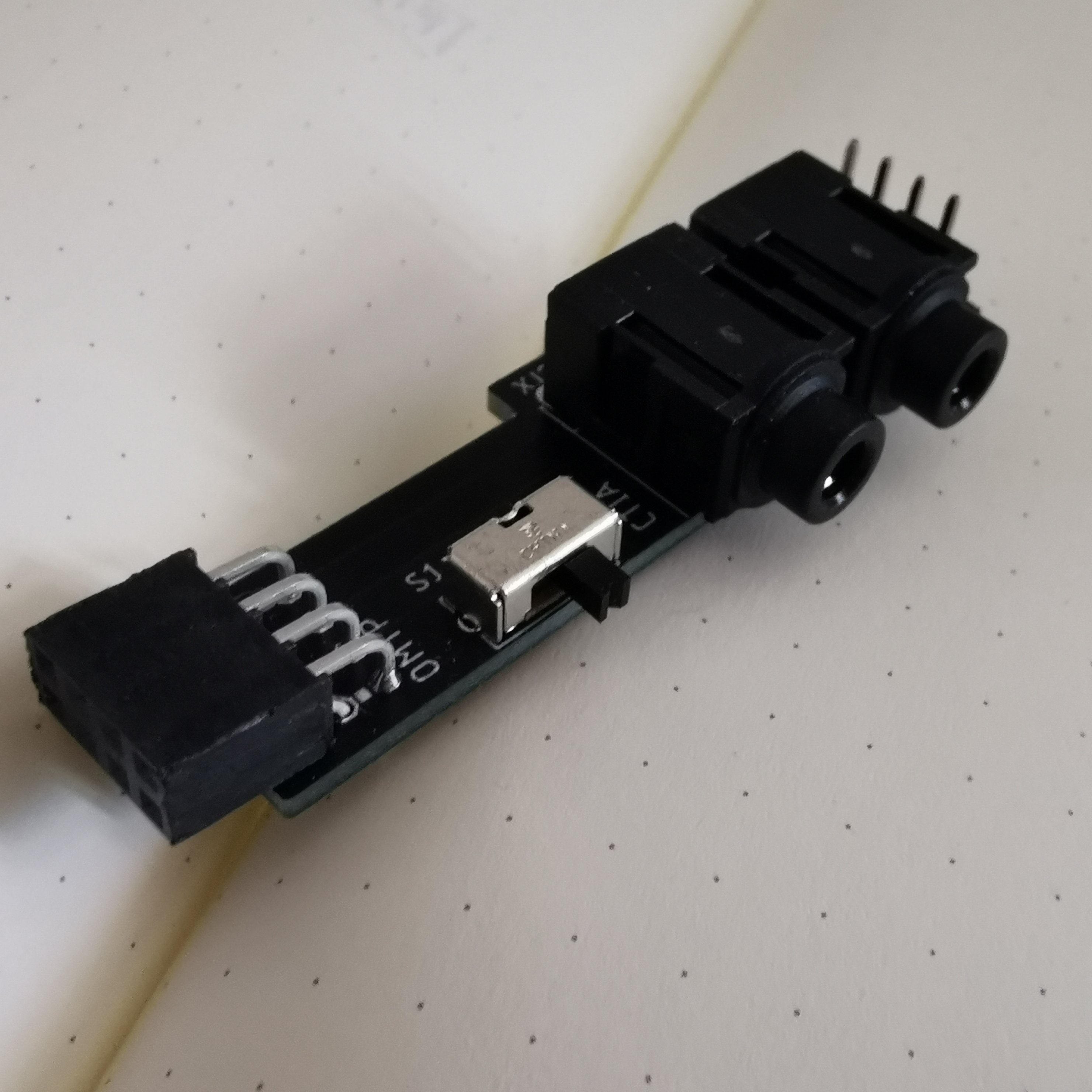
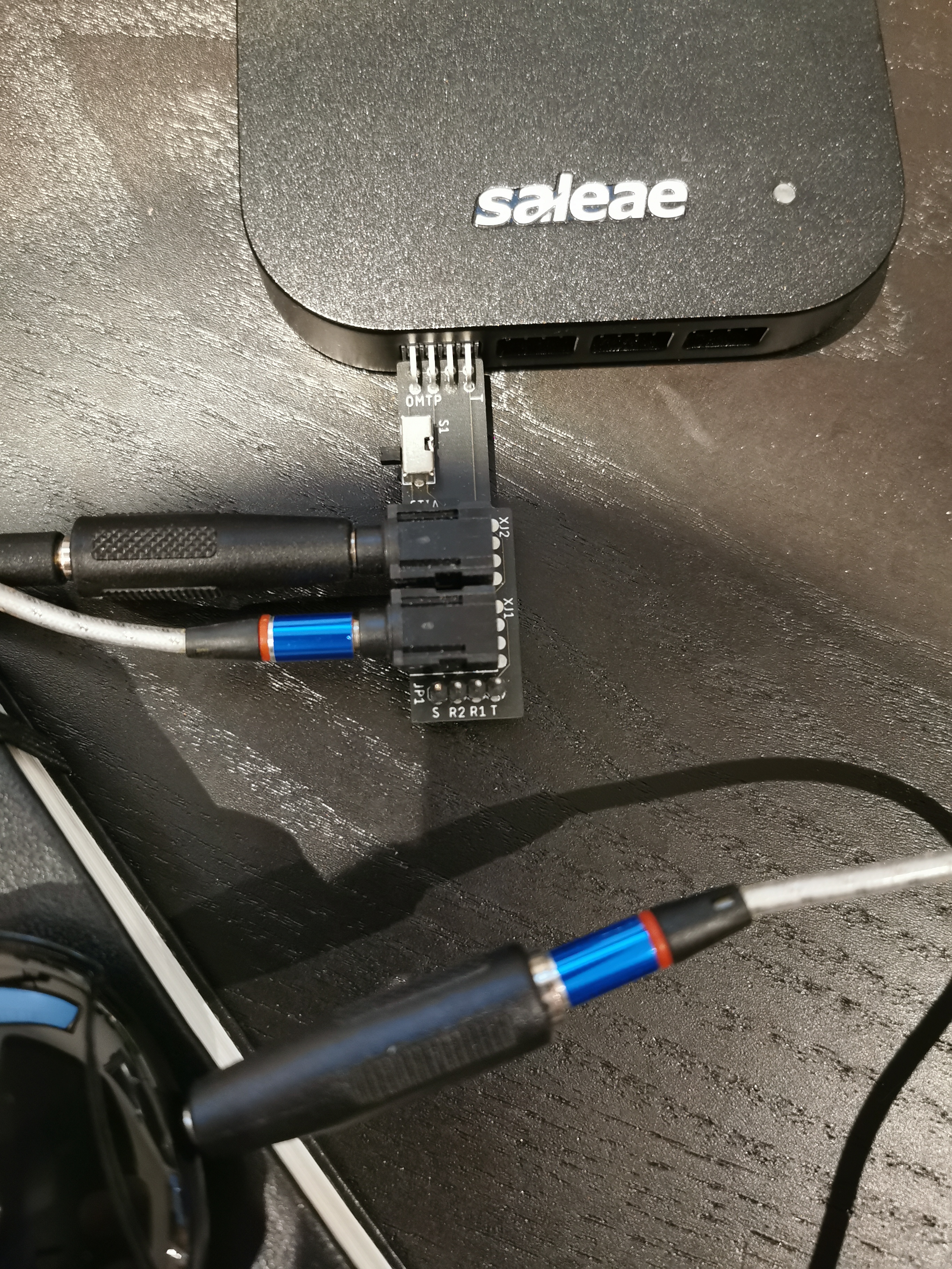
As you can see from the image on the right (or the bottom on mobile), the main use I have for this is to be able to observe the transmission between computers and glucometers, since that has been my main target for reverse engineering over the years, and very often they are connected via a TRS 2.5mm or 3.5mm serial plug, similar to how Osmocom has introduced the world of open hardware many years ago.
The board is simplistic, but also provides a few features to make my life easier. First of all, it uses TRRS connectors, because they are compatible with the good old TRS connectors, but also support more modern ones. Secondly, it’s only 3.5mm plugs on purpose: finding 2.5mm cables is annoying, but finding 3.5 to 2.5 and vice versa is easy, and that’s why I use it with those cables at the end.
Finally, killer feature for me is that switch, which selects between CTIA and OMTP ordering of the connectors. If you’re not aware of it, over time two separate standards have been in use for wiring four conductor TRRS cables, with one of them often incorrectly referred to as “Android” or “Samsung” and the other referred to as “Apple”. The CTIA/OMTP naming is the correct naming, and basically what this does is just changing which of the two pins of the connectors is provided as ground to the Saleae.
Oh yeah and eventually, I released it. I did that under 0BSD, because it’s a really obvious design and if someone wants to reuse it, I’m only happy. I have considered whether this should be released under the CERN Open Hardware License and I can’t imagine why, but if you want to make an argument for it I’m likely going to be swayed by it, feel free.
I also originally drawn plans for a USB-to-Serial adapter using CP2104 — in two versions, one that would just be a simpler USB-to-UART with no level shifting, and one that would be a full-blown level shifting RS-232 port. The latter was something that came to me as an idea after reading a lot Foone on Twitter, to the point that I sent them a some of the untested boards (because I got stuck with the move and stuff, so it took me months to get back to them!)
Unfortunately, something didn’t work out quite right. The serial adapter didn’t work out at all in my case, and the RS-232 one keeps browning out, probably because I skimped on the capacitors. I would be ready to get a respin to try this again, but the current chip shortage does not allow me to make more orders for SMT boards with that particular chip in it.
Serial Adapters Harnesses
Not quite related to the Saleae, but related to the recent work on my aircon reverse engineering, was starting to think about labelled wire harnesses for serial adapters. And thanks to Meowy’s reply (now gone) I went down the rabbit hole looking at professional label makers.
Now, let me be clear, I have had a label maker for quite a long time. I have blogged about it in 2011, when even the simplest of the label makers (Dymo LetraTag) was to be considered a risky investment (that’s what happens when you’re self-employed, coming from a blue-collar family, and in the backwaters of everything — one day I need to write more about that). I still use that label maker, pretty much our whole spice cabinet depends on it.
But there’s a different class of label makers, namely electricians’ label makers, such as the one showed off in the Big Clive video on the side. Of all the features that he shows off on that video, though, it was missing showing off prints on heatshrink, and how you can use those to make those labelled harnesses as shown in the tweet.
So, while the original price I could see (£110) was a bit annoying to invest for something I wasn’t sure I would be using very often, following Clive’s advice of waiting for Toolstation having it at a discount (which it did, at £69) was worth it — well worth it for me. Though to be honest, I got some off-brand heatshrink cartridges.
So the first thing I did with these have been creating a wire harness for one of the USB serial adapters that I have been working on the aircon with:

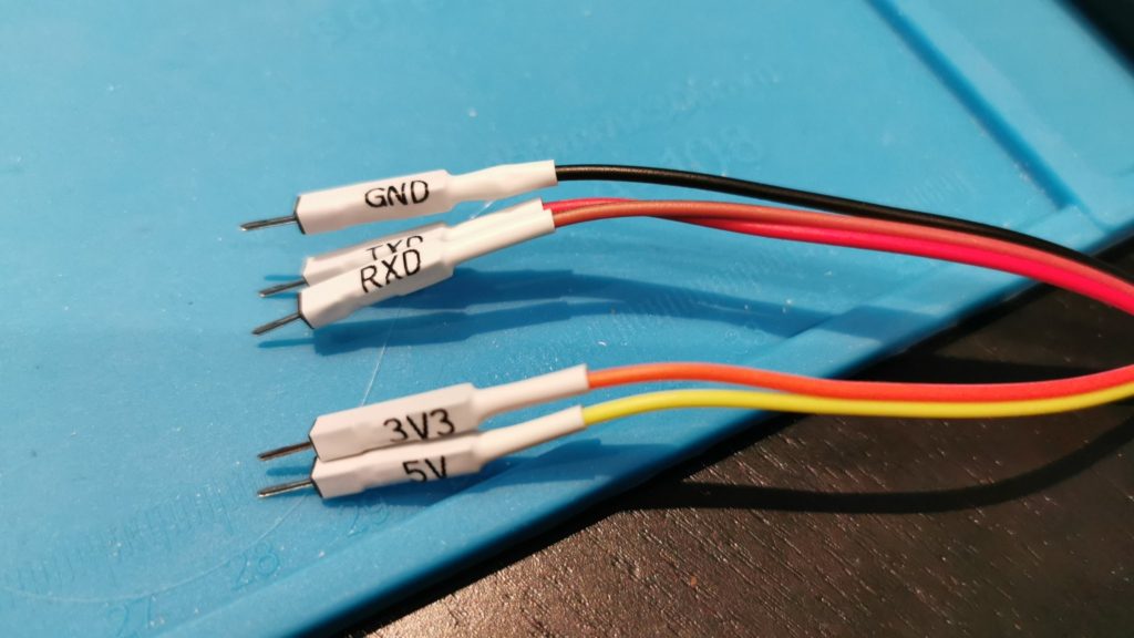
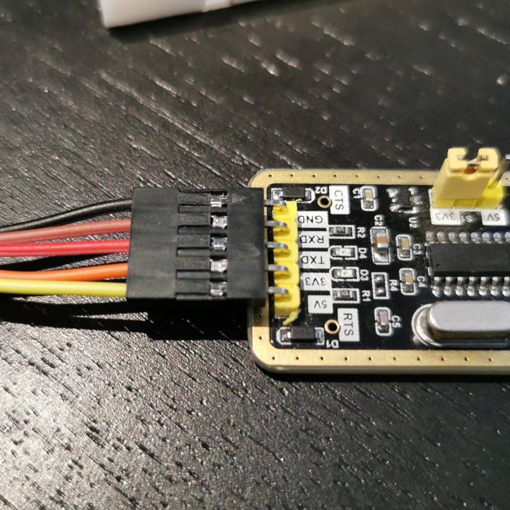
For this particular adapter, I also used a 1×5 Dupont plastic block — I did not crimp the cables, they come from a box of male-to-female cables that I bought off AliExpress some time ago, though you can refer to Big Clive on crimping, too. One of the things he shows in this last video, is that you can just break the plastic tooth to release the metal Dupont connector. Which is what I did: I broke off the plastic teeth, and re-fit the already crimped cable into the 1×5 housing.
I could have just prepared my own cables, to be honest. But to be honest, if I wanted to do that I would probably grab some good quality soft cables like the one that comes with the Saleae Logic, but I don’t have any of that stuff at home.
The other important part with this is that I used male-to-female on the cables, because these are the cables I need right this moment, because I’m working on the air conditioning reverse engineering, and that means I need to connect the serial adapter straight into the breadboard.
So About That Breadboard
You may have noticed one thing I said: I’m currently working on the aircon reverse engineering with breadboards, so having the cables end with a male connector helps. If you’re familiar with the Saleae Logic, you would know that the harnesses it comes with are 2×4 dupont cables with a female end to connect to boards. Which works great when you’re connecting to I/O pins on a board, or using the provided probes — but not really if you’re doing work on a breadboard.
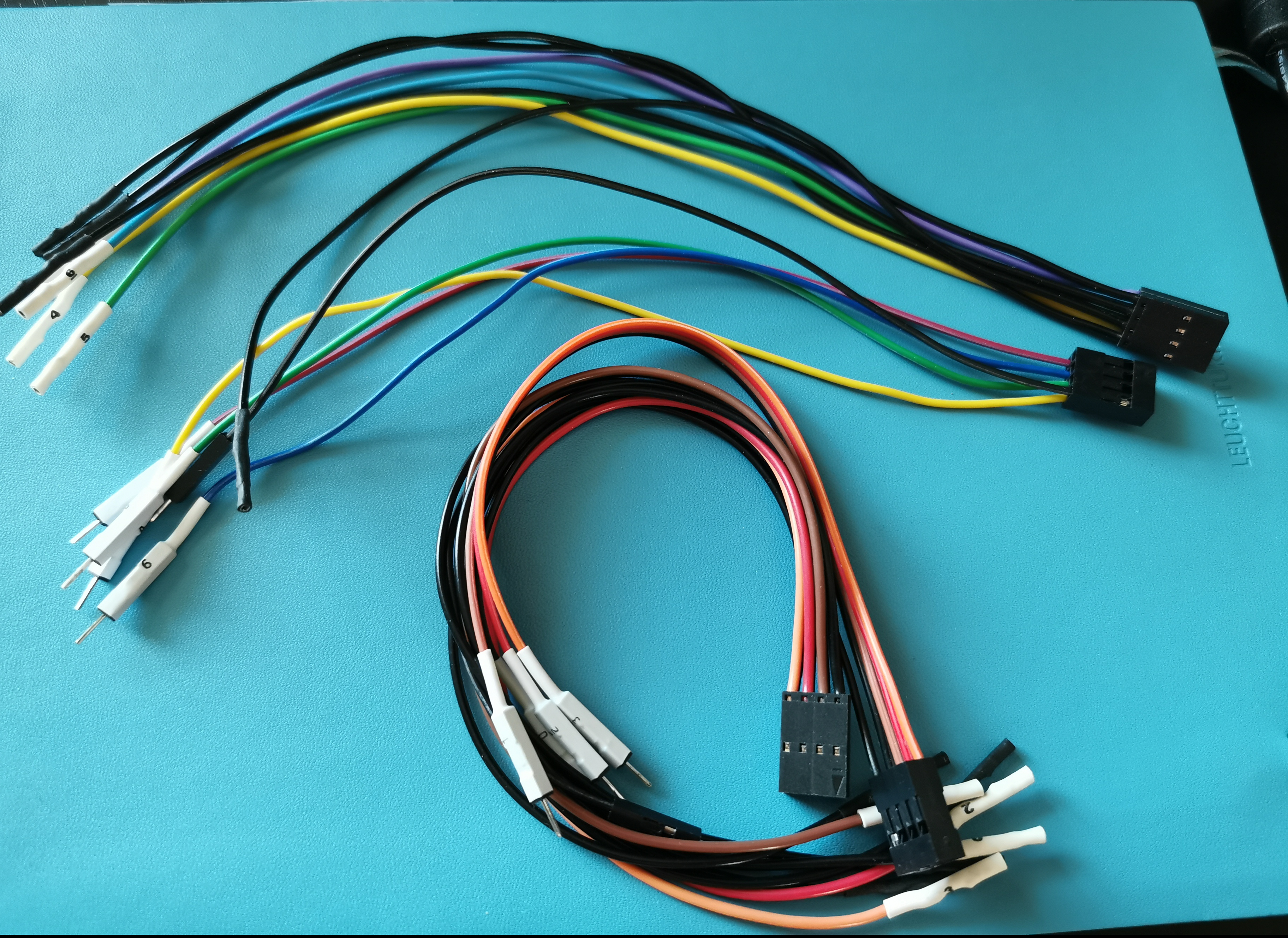
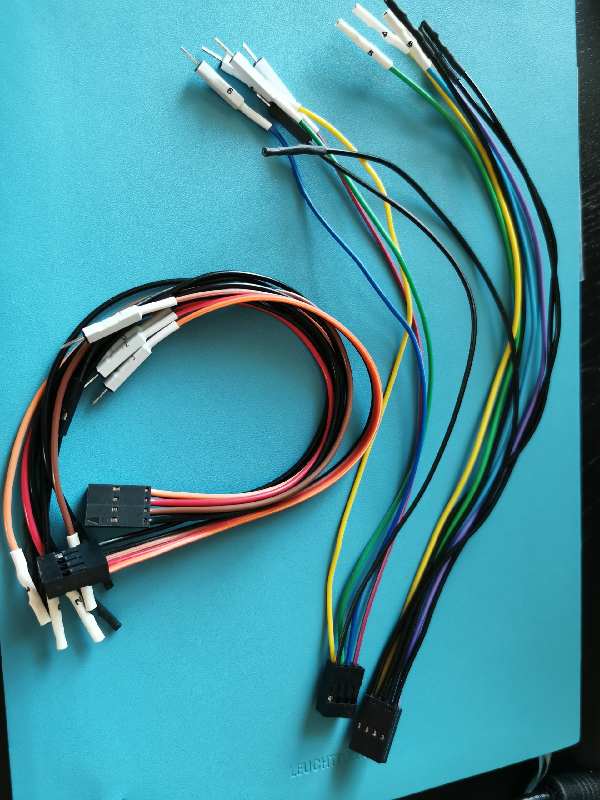
So in the same vein as I did for the serial adapter above, I also decided to go ahead and make my own set of additional harnesses. They are once again not perfect, as the cables are the same AliExpress cables I used for the other harness, but they will do the job for the time being.
I have kept the colours the same – or at least the closet that I could get to with the AliExpress cables – because the Logic software uses the colours to represent the channels. And that means I don’t need to worry anymore of matching colours with colours all over the place. On the other hand, since working with a breadboard means I don’t have that many different ground positions, I decided to only put one ground wire per block. This is also because I ran out of black cables in the pile of AliExpress ones (I should order more).
This turned out to be extremely useful. Being able to just grab the cables and plug them straight into the breadboard on one side, and the Logic Pro on the other made has been a huge timesaver during my work, both off-camera and during streams.
A Note On Board Design
After this experience, I also want to share some of the considerations I made my mind up on, after these trials and errors. The first is that it’s very hard to find more than 1×8 Dupont connectors. That means that in many, many cases it’s much easier to go ahead and use 2×5 connectors if you have multiple pins that need to be connected together.
It also makes sense to space them to “key” them as a single connector, rather than using multiple, out of line pin lines, which I have done in the past. Indeed, in the custom CP2102 that I spoke about earlier, I wouldn’t be able to have a single harness, and would rather need two. That was a bad idea for a design, and when I’m going to re-do it (because I am going to re-do it), I’ll make sure the pins are arranged 2×4 instead, so that it can be connected with a custom labelled harness… or one of the harnesses that comes with the Logic!
This is the kind of important and useful notes that I like reading, finding in videos, and I wish would be collated in more practical material for wannabe PCB designers. It definitely carries over on my current designs of the air conditioning control board.
Customizing The Software
In addition to the custom hardware dongles I’ve been playing with, I also started looking at using more advanced software for the analysis.
In the Software Defined Remote Control repository, I already had a binary that would be able to receive a CSV exported by Logic and interpret it. Unfortunately for this to be easily parsed from within Logic, I would need to write a C++ extension for it.
On the other hand, for the air conditioning, I just needed to write a Python High-Level Analyzer, which provides me with at least a bit of the understood meaning of the various bytes in the packets.
I hope that as time goes on, and I find myself reverse engineering different hardware, I will be able to build up a good library of various analyzers — hopefully sharing enough code between them. Which is something I definitely need to engage with Saleae on: it does seem like right now you cannot depend on external Python modules even from HLAs, but it would make sense to be able to use libraries like construct, or even higher level libraries for things like my aircon or some of the glucometers I have worked on before.