
This is part two of my tale of reverse engineering the air conditioning control panel in our apartment. See the first part for further details.
If you are binging on retrocomputing videos like I’ve been doing myself, you may have the wrong impression that a bus has to have multiple lines, like the ISA and PCI buses do. But the truth is that a single-wire bus is not unheard of or even uncommon. It just means that the communication needs to be defined in such a way that there’s no confusing as for who is sending at any given time. In this case, it’s clear that the control panel is sending six bytes which are immediately (and I do mean immediately) followed by six bytes response from the HVAC.
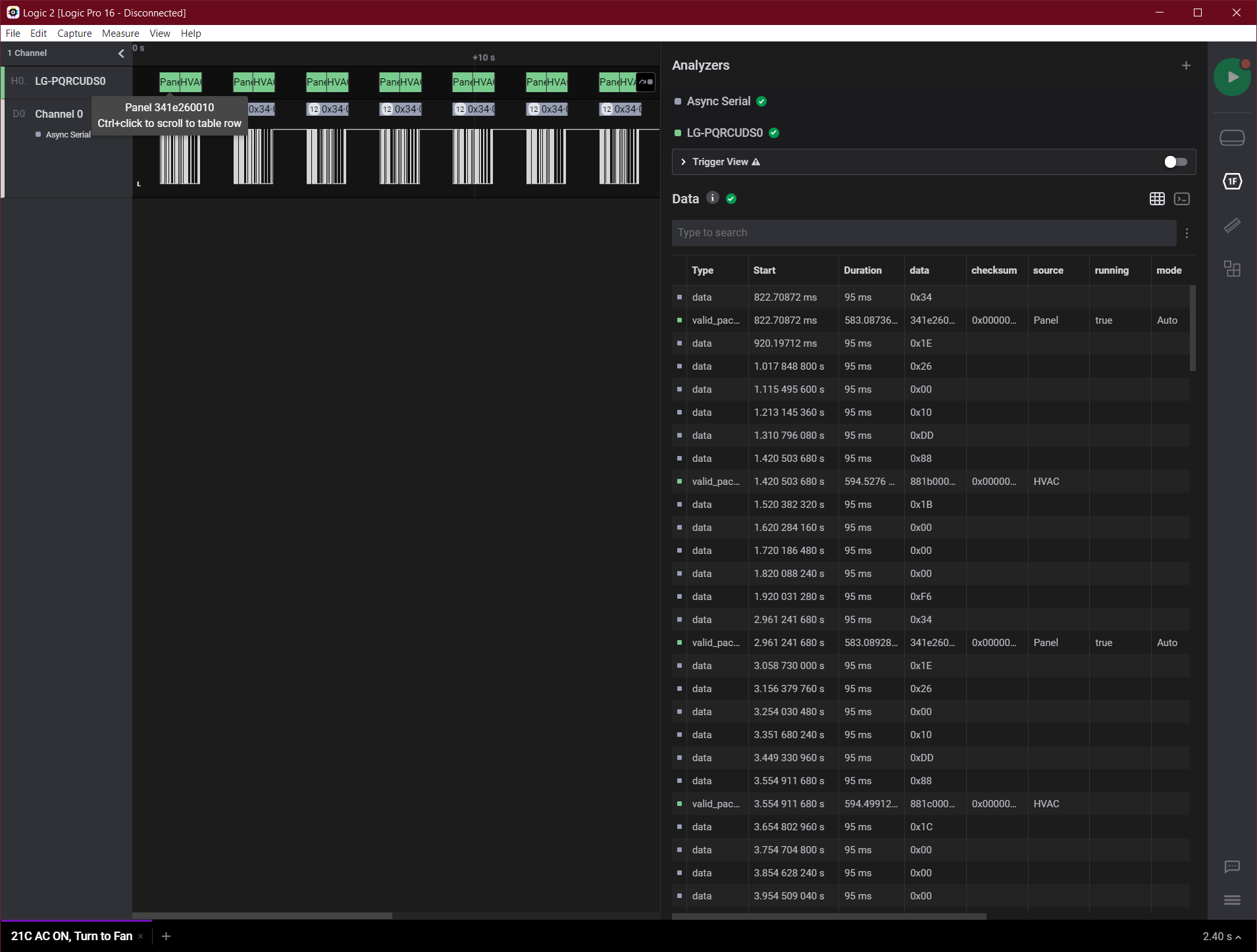
So the next step was to figure out what those six bytes where, and thanks to Saleae’s recent licensing of sample high-level analyzers, this became a piece of cake. While I’m not at liberty to share the code, at the time of writing, I ended up writing an analyzer that would frame together the 6 bytes from the panel and the 6 bytes from the HVAC. Once I had that, it was also easier to notice that the checksum byte was indeed the same as other LG protocols, it’s just that it applied separately to the two 6 bytes packets, which means there’s only five bytes in the message that need to be decoded.
With a bit of trial and error, I already decoded what I think will give me most of the important controls for my plan: how to change the mode between the aircon, heat pump, fan, dehumidifier, and how to change the fan speed. The funniest part is that the “Auto” mode is actually not a mode at all, and just means that the thermostat appears to be sending the “aircon” or “heat pump” as needed.
What got even more interesting, is that if you leave the control panel by itself, after a few minutes it appears to notice the lack of an HVAC connected, and goes into an error state where it alternates the display between “Ch” and “3”. Either it’s reporting its own channel for diagnostics (assuming it’s misconfigured) or it’s just showing a particular error status. In either case, that threw a spanner in my plans.
The first problem is that obviously you wouldn’t be able to connect the 12V data wire to the ESP32 directly. That’s kind of obvious: the ESP32 is a 3.3V microcontroller, and if you tried to use a 12V wire with it it’ll just… go. My original intent was to use two optocouplers: one to receive the data from the control panel, and the other to inject my messages onto the wire. But that won’t work quite the same way for a bus, and while I could try to build up the right circuitry with discrete components, I would have rather used a ready-made transceiver.
The problem with that the transceivers are made for specific buses, and so the first question is to find the right bus that is by LG. A lot of HVAC systems (particularly in industrial scale) use Modbus over RS-485 — I have experience with this since the second company I ever worked for is a multinational that works in the industrial HVAC sector, so I learnt quite a bit of how those fit together. But an RS-485 connection would require two wires, since it uses differential signaling, and that’s already excluded.
Going pretty much by Google searches, I finally nailed down something useful. In the automotive industry, there’s a number of standards for on-board diagnostics (OBD). The possibly most famous (and nowadays most common) of those is the CAN bus, which is widely used outside that one industry, as well. LG is not using that. But one of the other protocols used is ISO 9141-2, which includes a K-Line bus on it, which according to Wikipedia is an asynchronous serial connection over a single bidirectional wire without handshakes — though it is using a 10.4kBd signal which is… exactly 100 times faster than the LG signal.
Through these, I found out about the LIN (Local Interconnect Network) bus, which is also used in automotive, specifies a higher level implementation on top of ISO 9141 compatible electrical signaling, but happens to be a good position to start the work with. Indeed, there are a number of LIN bus transceivers that are pretty oblivious of the addressing and framing on the protocol — on purpose, because the specifications have changed over the years. But what they are good for, is to connect to a 12V, high recessive bus, and provide microcontroller-leveled RX and TX signals.
An example of these transceivers is Microchip’s MCP2003, so I decided to set myself up to redesign the board based on that. But since the control panel also needed to receive “acknowledgements” from the HVAC, it meant that each “smart controller” needs two transceivers: one where it fakes the controller to the HVAC, and another one where it fakes the HVAC to the controller. And both of those needed to have the ability to just go into a “lurking” state where they wouldn’t be sending signals if I flipped a physical switch.
Screw It, I’m Doing It Live
So here’s where things got a bit more interesting in multiple directions. In the days just before this work, I was being asked a few pointers about reverse engineering — and unfortunately I don’t know how to “teach” RE, but I can at least “go through the motion”. After all, that was the more interesting part of my Cats Protection streaming week, so once the DigiKey order arrived with the transceivers and all the various passives to add around it, I decided to set up a camera, and try breadboarding the basic circuitry.
Now, setting aside the fact that I do not particularly enjoy streaming with an actual camera, and indeed the end results left a lot to be desired, the two hours stream was fairly productive. I found that the PL2303 USB-to-serial adapters actually work quite well at both 100 and 104 Bps, and that indeed the transceiver mostly works fine.
It also showed an interesting effect that I did not expect: as I said earlier, after a few minutes without getting an answer from the HVAC, the control panel enters into an error state (Ch/3). I assumed that what it needed was a valid packet from the HVAC, with checksum and information. Instead, it seems like just filling up a buffer, even with invalid packets, is enough to keep the control panel working: as I typed random words onto the serial port, while connected to the bus, the Ch/3 error vanished, and the panel went back to a working state.
This was surprising for one more reason: at least some of the packets sent from the HVAC to the panel had to include the capabilities the HVAC system has to begin with. The reason why I knew that is that the control panel appears to have a lot more functions when it’s running standalone, compared to when it’s installed on the wall. Things like a “power” fan mode for the aircon, the swiveling ventilation, and so on.
Spoiler: it turned out to indeed be the case: the first two commands sent from the panel to the HVAC appear to be some sort of inquiry, that provide some state to the panel to know which features are supported, including the heat-pump mode and the different fan speeds. But for now, let’s move on.
Before I could go and and try to figure out which bit related to which capability I hit a snag, which is what I got stuck at the end of the stream there: sending the character ‘H’ on the serial port (a very random character that just happens to be the start of the string “Hello, world!”) showed me something was… not quite right.
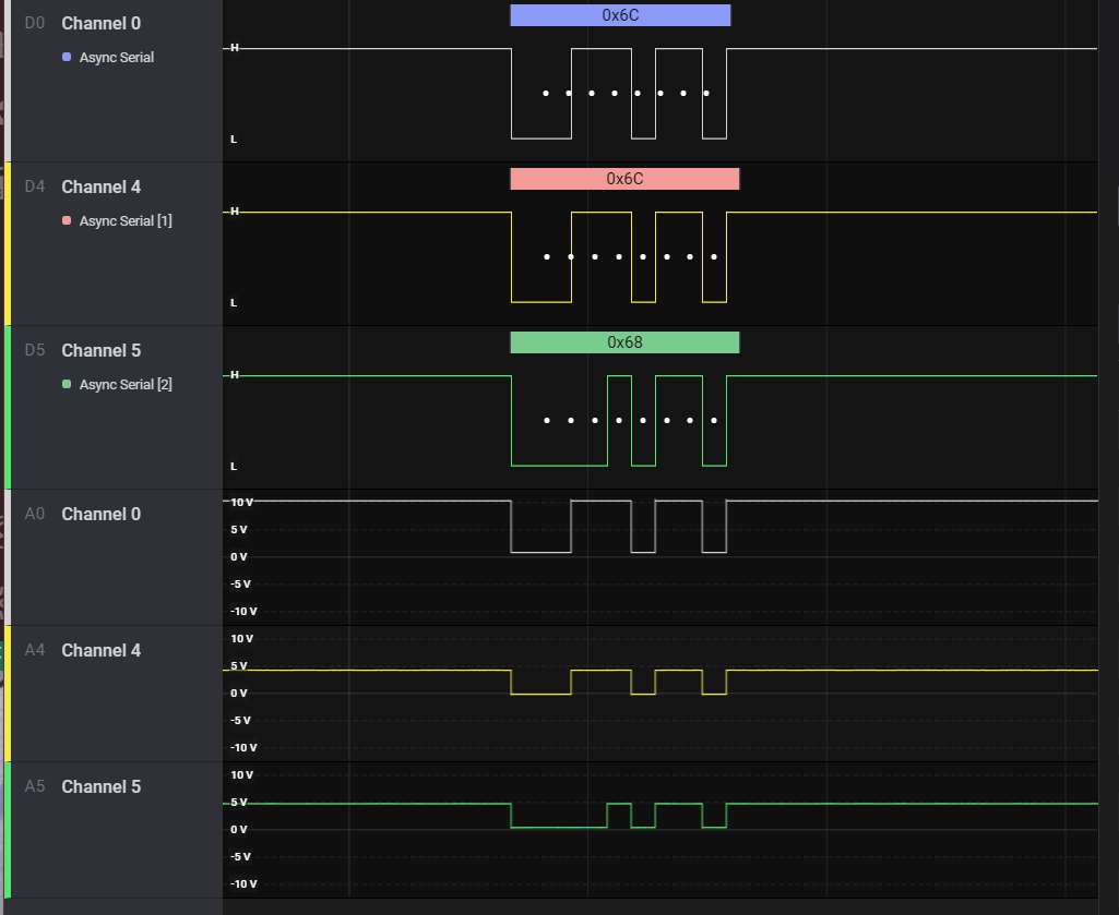
This is not easy to see, beside for the actual value changing, but in the image above the first row (Channel 0) is the 12V bus (which you can read on the fourth line is actually 10V), the second and fifth rows (Channel 4) are a probe connected to the RXD pin of the MCP2003, and the third and sixth (Channel 5) are a probe connected to the TXD pin (which is in turn connected to the TXD of the USB-to-serial adapter).
Visibly, the problem is that somehow the bus went from “dominant” (0V) to “recessive” (12 10V) too fast, making the second and third bits look like 1s instead of 0s. But why? My first thought was that it was an electrical characteristic I missed – I did skimp on capacitors and diodes on my breadboarding – but after the stream terminated, I grabbed my Boox, and checked the datasheet more carefully and…
1.5.5.1 TXD Dominant Time-out
If TXD is driven low for longer than approximately 25 ms, the LBUS pin is switched to Recessive mode and the part enters TOFF mode. This is to prevent the LIN node from permanently driving the LIN bus dominant. The transmitter is reenabled on the TXD rising edge.
MCP2003/4/3A/4A Datasheet, DS20002230G, page 10
25ms is nearly exactly how long the dip to dominant state is on Channel 0 (and about the same on Channel 4): it’s also nearly exactly 2.5 baud.
A Note About Baudrate
I have complained loudly before of how I’m annoyed at people who think those younger than them know nothing and should just be made fun of. I don’t believe in that, and I think we should try our best to explain the more “antique” knowledge when we have a chance.
Folks who have been doing computers and modems well before me appear to love teasing people about the difference between “baudrate” and “bits per second”. The short version of that is that the baud rate relates to the speed of sending a single impulse, while the bits per second (bps) is (usually, but not always) meant to be taking the speed of the actual data transmitted. The relation between the two is usually fixed per protocol, and depends on how you send those bits.
In a asynchronous serial protocol (including RS-232 and this LG abomination), you define how you send your bits with an expression such as “8n1” or “7-odd-2” (also called the framing parameters) — or a number of other similar expression with different values in them. These indicate that each character sent is respectively eight or seven bits in size, that the parity is not present in the first case, and is odd in the latter, and that the first includes only one stop bit while the second is providing two. In addition to this, there’s always a single start bit.
8n1 is probably the most common of the framings, and that means you’re actually sending 10 bits for each character. A baudrate of 9600 Bd/s gives you a 960 bps raw connection, the 104 value for LG is the actual baudrate, as I can measure one of the impulses from the original control panel at 9.745ms — which actually would put it around 103 Bd/s.
Which is where my assertion that 25ms is nearly exactly 2.5 baud — 2.65 to be a bit more precise: you take the length (25) and divide it for the time needed to send a single baud (0.9745).
What this means in practicality is that the MCP2003 series (including the more modern MCP2003B that includes the same time-out behaviour) has a minimum baud rate as well as a maximum one. The maximum one is documented in the datasheet as 20 Kb/s, but the minimum is affected by this timeout: a frame of all zeros would be the worst case scenario in this condition, as the line would be asserted low (“dominant”) for the longest time. While theoretically you can define framings the way you prefer, the common configurations vary between 5 and 9 data bits per frame (though I would have no clue how to process the 9 bits per frame to be honest!) — which means that the maximum number of space (‘0’) baud would vary between 6 and 11.
Why six and eleven? Well, the “start” baud is also a space (logical zero) – which means that if your framing is 5n1, the 0x00 value would be sent with six “spaces”. And if you use nine data bits per frame with even parity, 0x000 would then be followed by a “space” in parity (to maintain the number of ‘1’ bits even), bringing it up to 11 (start, nine zeros, and parity).
The minimum baudrate for a certain framing configuration is thus calculated by dividing the maximum number of consecutive spaces the timeout in seconds (0.025), which leads to a minimum baudrate of 240 Bd/s for when using 5n1, 440 Bd/s for 9e1, and 360 Bd/s for the most commonly used 8n1 framing. Which is over three times faster than what these LG units are using.
I Need A New Bus Transceiver
Since I couldn’t use the MCP2003, I ordered a few MCP2021. Note that Microchip also says that these are not recommended in new designs, suggesting instead the ATA663232 — which as I’ll get to has all of the disadvantages of all the various options for LIN bus transceivers.
When I received the meter, I decided to take another stab at streaming setting up the emulator on camera:
If you watch the whole video you will see me at some point put a finger on the chip and yelp — turns out I ended up with a near-dead short on its embedded regulator. Thankfully, since the chip is designed for the automotive market, the stress did not cause it to fail at all, just… overheat. And as I showed on stream, I did manage to keep the control panel running with my “emulator”, although I did note some noise on the I/O towards the end.
So a little bit more exploration later told me that a) the PL2303 seems to be a bit unreliable with the 3.3V without tying the VREG with the 3.3V coming from the device, and b) even on the CH341 I would get some strange noise in addition to the signal. I think the reason for that is that the chip uses a comparator against its own regulator to decide whether the transmitter should be on. Since, as Monty and Hector suggested, it’s a bad idea to tie multiple regulators together, I decided that even the MCP2021 is not the transceiver I wanted.
Unfortunately, that made it harder to find the right transceiver. Microchip’s suggested replacement, the ATA6632xx series, has all of the disadvantages, as I said: it has the “TXD Dominant Timeout” feature (so it cannot send the 104bps signal I need to send), it includes a voltage regulator that cannot be disabled, and it is only available in VDFN package that is not possible to hand-solder.
On Digi-Key (which is by now my usual supplier), Microchip’s MCP20xx series are the only PDIP-8 through-hole components, so the next best thing is SOIC-8, which is surface mount (so not easily breadboardable) but still hand-solderable (with a steady hand, a magnifying glass, and a iron tip). Looking at those, I found at least two that fit.
ON Semiconductor’s NCV7327 was a very obvious choice because they explicitly say in the features list «Transmission Rate up to 20 kbps (No low limit due to absence of TxD Timeout function)», and it was the only one that I found explicitly note that the TxD Timeout imposes a floor to the speed (as I explained above). Unfortunately, the SOIC-8 version was not available at the time of order on Digi-Key, with a 22 weeks backorder.
So instead, I settled for Texas Instrument’s TLIN1027DRQ1. This is pretty much… the same. For what I can see, both ON’s and TI’s SOIC-8 devices are pin compatible, and they are nearly pin compatible with Microchip’s SOIC-8 variants, insofar as the power, bus, RXD, and TXD pins are in the same position.
There is, though, a rake just waiting for you there. The Enable/Chip Select pins on both the TLIN1027DRQ1 and the NCV7327 do not correspond to the MCP20xx Transmission Enable semantics, despite sharing the same position. With the MCP20xx you could leave a transceiver connected to a chatty bus, with the TXEnable off, and you would still receive the traffic from the bus.
But with the other two, you’re turning off the whole transceiver at once, which wouldn’t be too bad if it wasn’t that both of these pull TXD to ground (dominant), if you leave it unconnected. Again, this isn’t a big problem in by itself, as long as the firmware is told not to transmit when the bus is connected directly between the panel and the HVAC, nothing should be transmitted, right?
But this does break one assumption I was making: if I disable the smart controller board, I want to be able to remove the ESP32 devkit altogether. This is important because beside OTA (Over The Air) updates, I would need to be able to disconnect the ESP32 to update the firmware on it. Which means I don’t want to rely on the firmware being running and not holding the bus busy.
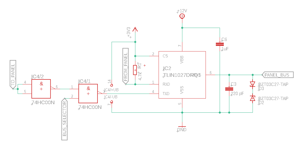
So what I ended up adding to the design is a way for the bus selector to decide whether transmission is to be allowed on the transceiver. I think this is the first time I even consider the idea of using a 74-logic component in my designs (to the point that I had to figure out how to use that with the EAGLE-provided symbols — hint: use the invoke command), but this seemed to me as the easiest option to implement what I needed.
The tie-up-both-inputs for the NAND is literal textbook electronics, but turns out to work very well since the cheapest 74 logic NAND chip I found contains four of them, and I only need one other.
Note that of course this is only one of the “logical blocks” of the board — and actually not even the final form of it. As I get into more details later, you’ll find out that this only turned out to be one of the possible solutions, and (at the time of writing) there’s no guarantee that this is actually going to be the one I’m going to be using.
Great read, thanks. I’m increasingly invested in this challenge.
Next time you see somebody teasing victims about the baud thing, please inform them that in addition to being rude, it is also wrong.
Baud is the cycles per second of the relevant signal, if you are looking at, say, a 1200bps modem with a scope it is important to know that it is running at 300 baud with 4 bits encoded in each cycle.
The 10 bits to get 8 thing is usually referred to as framing overhead. Sometimes people call it things like gross/net bit-rate.