You may remember that, by now, over three years ago I spent some time investigating the type of acrylic lamps that are easily found on Amazon and AliExpress — which are effectively the same that Techmoan reviewed six years ago.
Originally, I wanted to design and publish a board that would fit in the bases I could buy already made, but besides the constraints being harder to work with, I stumbled across multiple problems that ended up wasting quite a bit of time (and money, but mostly time) and eventually my time ran out and I had to set this aside. I came back to it this year and decided to reduce the scope by designing a simplified version of the board: rectangular, ready manufactured by JLCPCB, and without a USB-to-UART adapter on board.
Going this route added costs (it required me to design, and get manufactured, a custom base for the board itself) but it also made the success bar a lot lower. And yet I managed to make mistakes in the first attempt, as I got the serial port lines incorrect for automatically resetting the board and entering into bootloader mode. But eventually it meant I managed to get something working!
I have, obviously, published the designs on GitHub. Unfortunately I know I’ll attract some negative feedback for having designed the whole thing with the proprietary AutoDesk Fusion 360, but… hey either this or nothing for me, at least at this point, I don’t have time to learn alternative software.
While I was hoping for this solution to be simpler, it did end up hitting a few more hurdles than I expected:
- The ESP32 module I originally designed these around is discontinued and not recommended for new designs; thankfully the ESP32-S2 SOLO module is footprint-compatible with the WROOM — with a few more GPIO pins which I don’t need, but with the serial port in the same position, but as it turns out with some of the lines’ names being different, which caused me quite the headscratcher when I tried to configure ESPHome.
- Finding a suitable USB-C plug was not easy. The problem was finding a plug that would be able to be assembled by JLCPCB, and of those I couldn’t find any that had a ready-made symbol. I ended up having to design my own symbols for… a couple of them, a few for power-only connections, and two for USB 2.0 data connectivity as well. Going from the PDF with mechanical drawings to the symbol is an experience and for the first time I’m glad I had two years of technical drawing in high school.
- After the first batch of 3D printed bases (which I ordered from 3D People in the UK), I corrected them to have slightly taller feet to hide the screw heads a bit better. The door of the base is still not easy to align, and I should probably find a different way around it, but for the short term it appears to work alright.

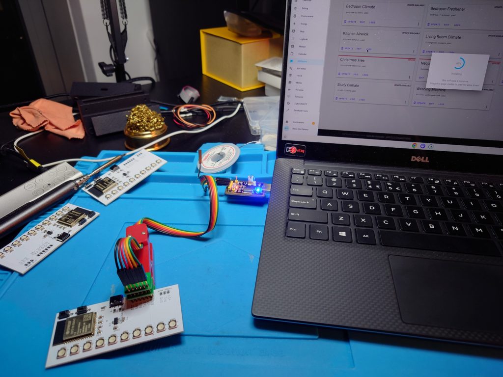
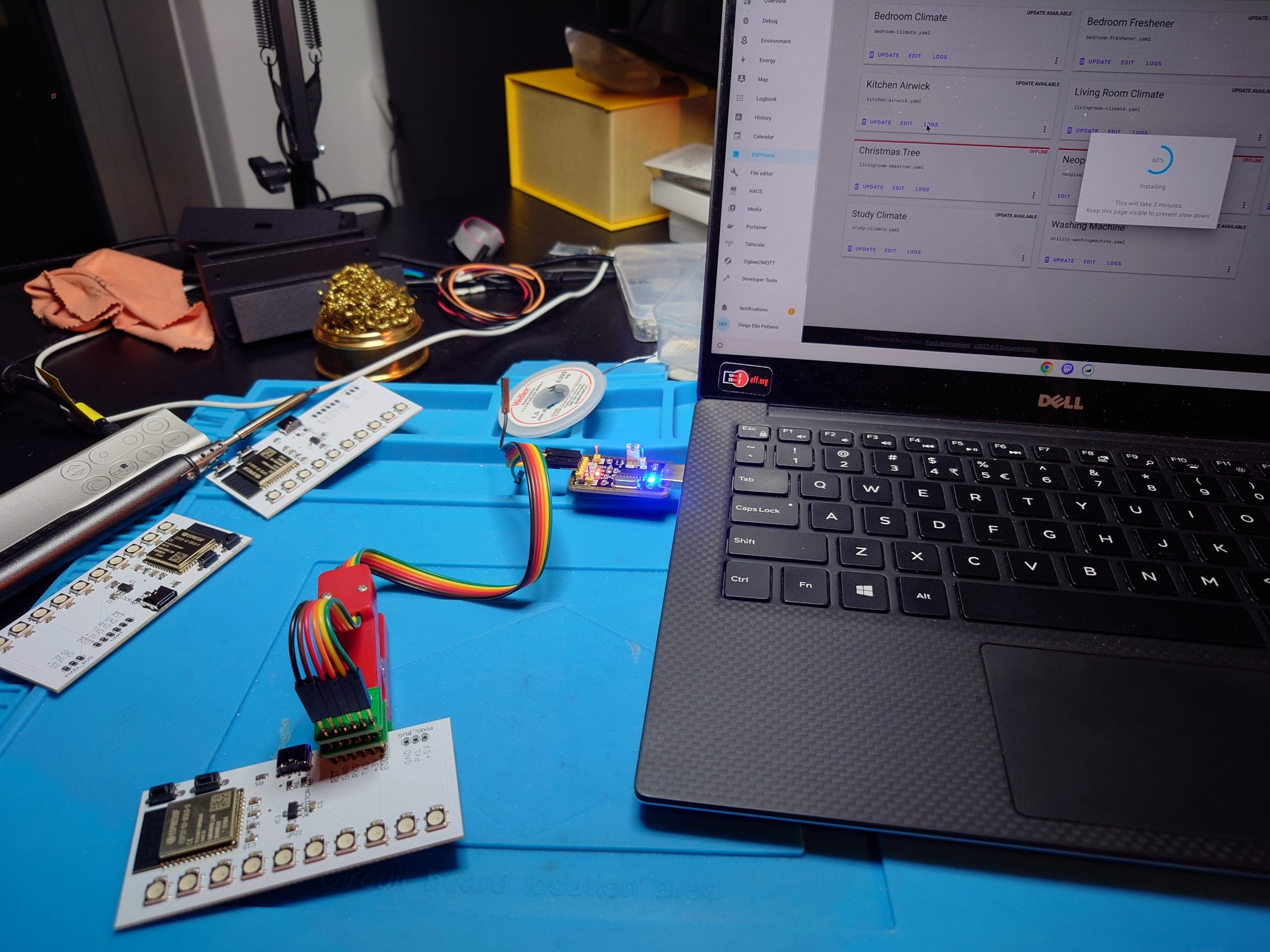
While, as I said earlier, the version of these board that I managed to get working does not include the automatic reset and bootloader mode (and indeed required me to solder in pushbuttons for be flashed), I was thankfully able to use one of those clamps with pogopins to program them. Indeed, as I posted on various social media, I could flash these after just soldering the buttons, and even doing so with my ChromeOS Flex laptop.
I have now re-designed the UART-less board to include the correct pinout for the automatic boot mode selection, but I have not tried getting it manufactured. Instead, I tried a new version with the serial adapter, based on the CH340C (which is familiar to me) which unfortunately… does not enumerate. I need to spend some time debugging what I did wrong with the CH340C wiring — or maybe I have a bad footprint for the USB-C plug.
What I’m still missing in the repository is a sample configuration for ESPHome. While I have it working right now, and I indeed set up my insulin reminder to go through Home Assistant now, but I have yet to figure out the correct parameters to make the rainbow and twinkle effects work correctly — ESPHome has them implemented already for a strip of addressable LEDs like the NeoPixels, with a few parameters to customize colours and timing. Once I have a good option for those it will all be added to the repository.
Over the next few weeks I hope to be able to debug and correct the UART-full board, as it would make development and DIY builds a lot easier: the pogopin clamp is great to keep the per-board costs down (no need to put USB-to-UART chips and related passives on each light, the USB power-only connector is cheaper, too) but if I was to give one of those boards to a friend I would have to pre-program it in that case.
Hopefully I’ll also be writing more blog posts to cover another electronics hobbyist project I spent some time on in the past couple of months, which I’m codenamed Gone with the Wind because I’m spending time on Zephyr — but that’s going to still take me quite a lot of time to be able to make sense of it, and I have very little to nothing to show for it.

