
A couple of months ago I built an insulin reminder light, roughly hacking around what I would call an acrylic lamp. The name being a reference to the transparent acrylic (or is it polycarbonate?) shape that you fit on top, and that lights up with the LEDs it’s resting on top. They are totally not a new thing, and even Techmoan looked at them three years ago. The relatively simple board inside looked fairly easy to hack around, and I thought it would make a good hack project to look more into them.
They are also not particularly expensive. You can go on AliExpress and get them for a few bucks each with so many different shape designs. There’s different “bases” to choose from, too — the one I hacked the Pikachu on was a fairly simple design with a translucent base, and no remote control, although the board clearly showed space for a TSOP-style infrared decoder. So I ended up ordering four different variants — although all of them without remotes because that part I didn’t particularly care for: one translucent base, one black base with no special features, one with two-colour shapes and LEDs, one one self-changing LEDs with mains power only.
While waiting for those to turn up, I also found a decent deal on Amazon on four bases without the acrylic shapes on them for about £6 each. I took a punt and ordered them, which turned out to be a better deal than expected.
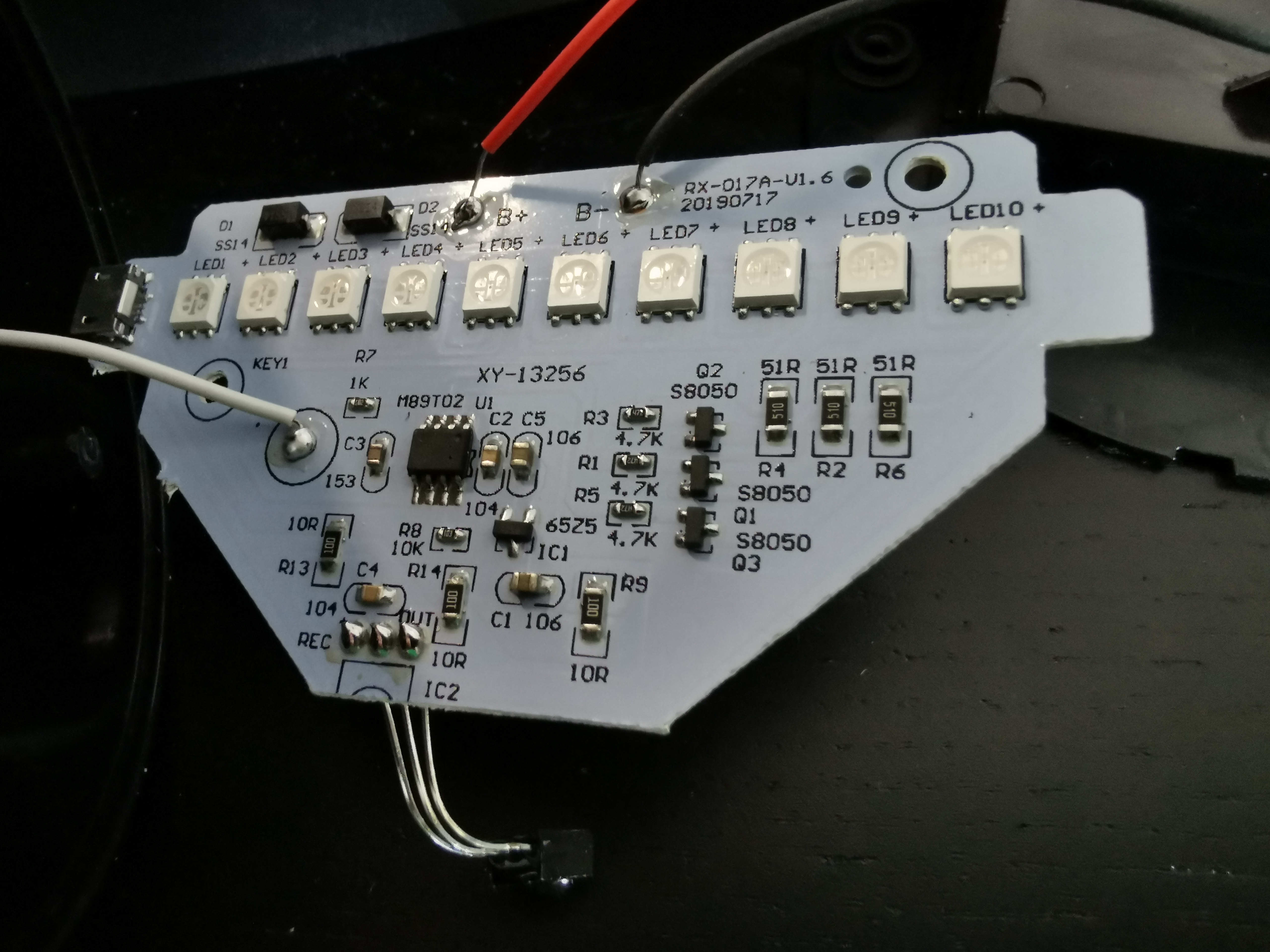
These bases appear to use the same board design, and the same remote control (although they shipped four remotes, too!), and you can see an image of it on the right. This is pretty much the same logic on the board as the one I hacked for my insulin reminder, although it has slightly different LEDs, which are not common anode in the package, but are still wired in a common-anode configuration.
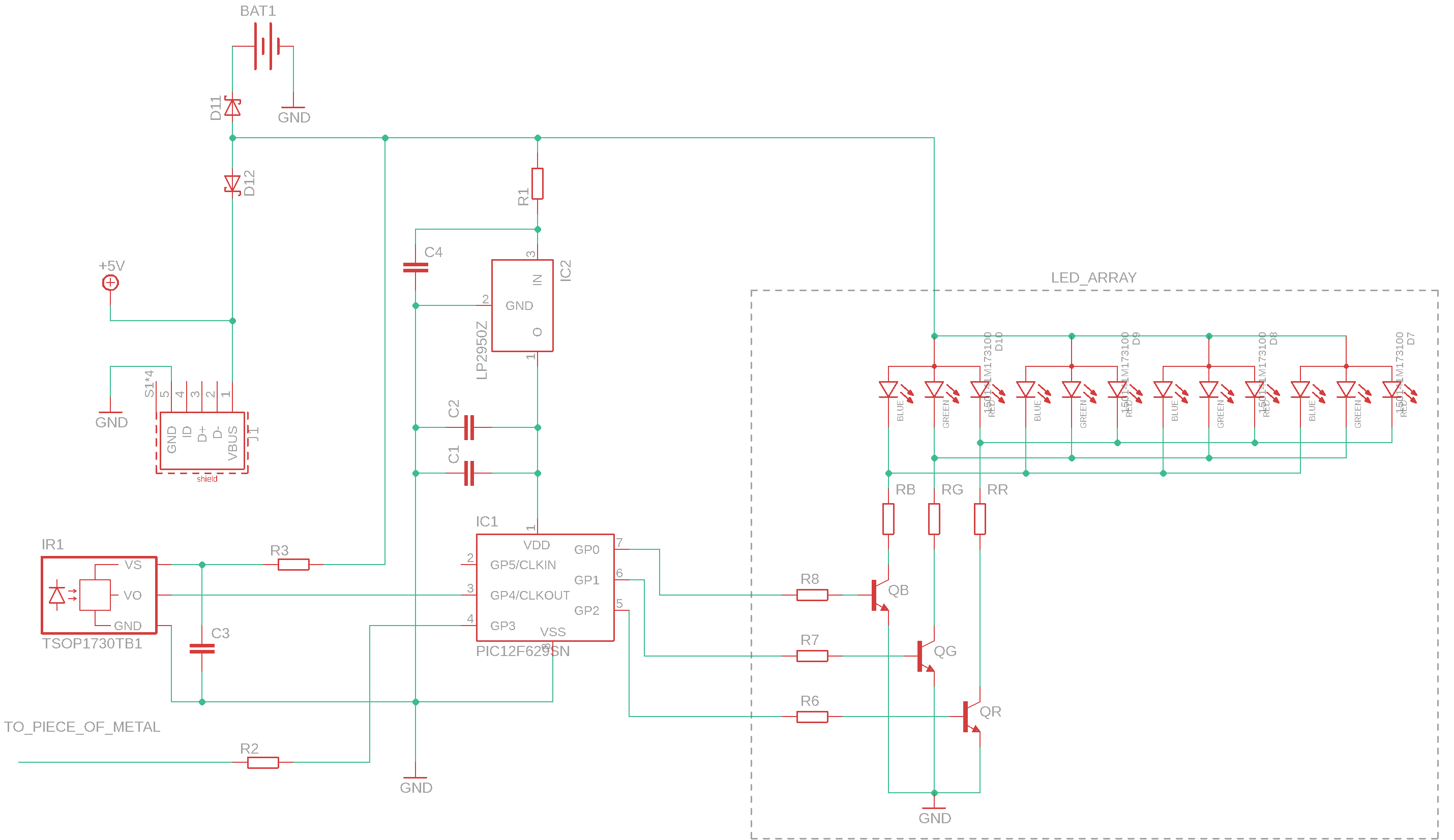
For both the boards, the schema above is as good a reversing as I managed on my own. I did it on the white board, so there might be some differences in the older green one, particularly in the number of capacitors, but all of that is not important for what I’m getting to right now. I shortened the array to just four LEDs to show, but this goes on for all of the others too. The chip is definitely not a Microchip one, but it fits the pinout, so I kept that one, similarly to what I did for the fake candle. Although in this case there’s no crystal on the board, which suggests this is a different chip.
I kind of expected that all the remaining boards would be variation on the same idea, except for the multi-color one, but I was surprised to figure out that only two of them shared the same board design (but took different approaches as to how to connect the IR decoder — oh yeah, I didn’t select any of the remote-controlled lamps, but two of them came with IR decoderes anyway!)
The first difference is due to the base itself: there’s at least two types of board that relate to where the opening for the microUSB port is in relation to the LEDs: either D-shaped (connector inline with the LEDs) or T shaped (connector perpendicular to the LEDs). Another difference is in the placement of the IR decoder: on most of the bases, it’s at 90° from the plug, but in at least one of them it’s direct opposite.
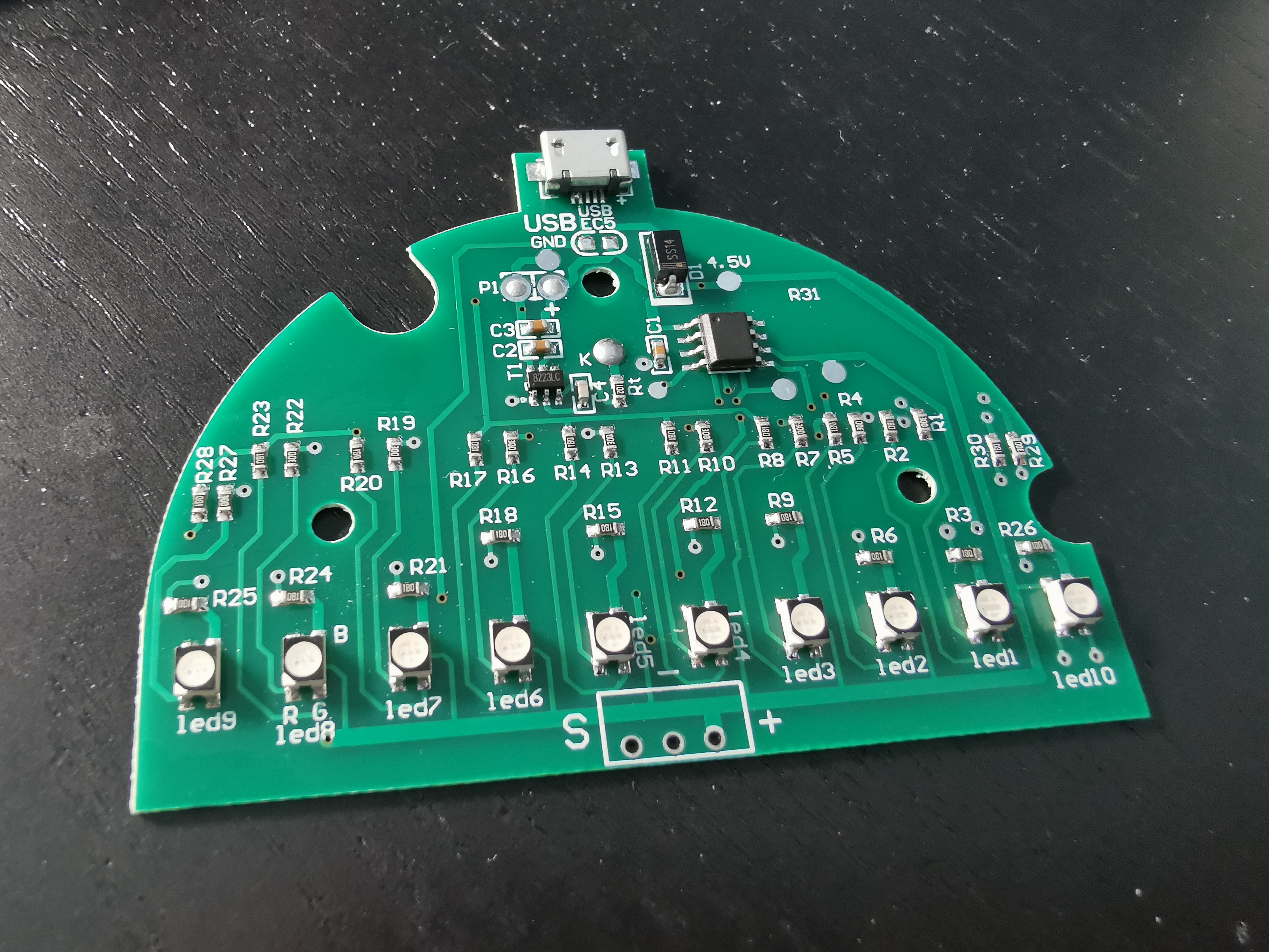
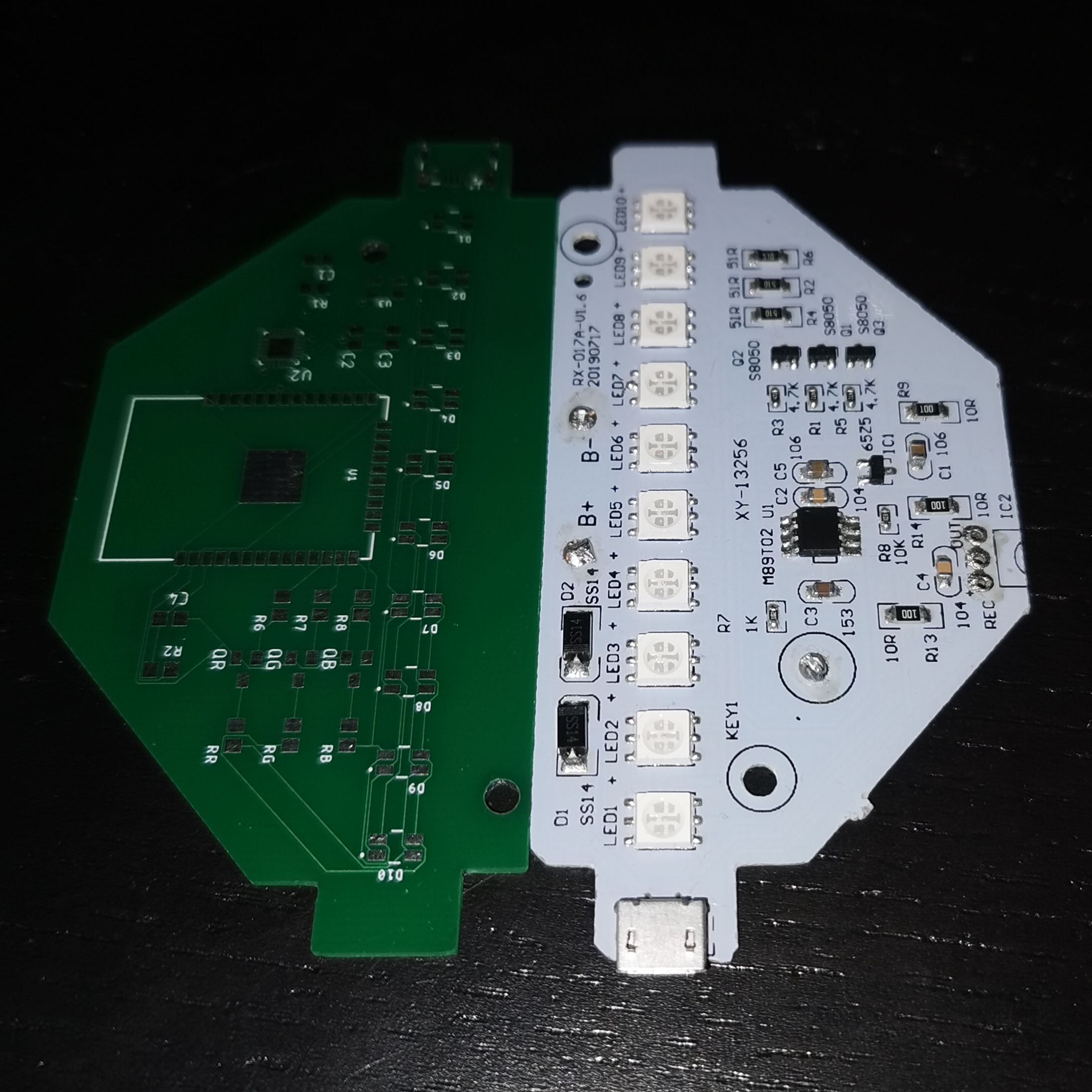
Speaking of bases, the one that was the most different was the two-colours base: it’s quite smaller in size, and round with a smooth finish, and the board was proper D shaped and… different. While the LEDs were still common-anode and appeared wired together, each appears to have its own paired resistor (or two!), and the board itself is double-sided! That was a surprise! It also is changing the basic design quite a bit more than I expected, including only having one Zener, and powering up the microcontroller directly over 4.5V instead of using a 3V regulator.
It also lacks the transistor configuration that you’d find on the other models, which shouldn’t surprise, given how it needs to drive more than the usual three channels. Which actually had me wonder: how does it drive two sets of RGB LEDs with an 8-pin microcontroller? Theoretically, if you don’t have any inputs at all, you could do it: VDD and VSS take two pins, each set of LEDs take three pins for the three colour channels. But this board is designed to take an IR decoder for a remote control, which is an input, and it comes with a “button” (or rather, a piece of metal you can ground with your finger), which is another input. That means you only have four lines you can toggle!
At first I thought that the answer was to be found on the other six-pin chip on the lift, but turns out that’s not the case. That one is marked 8223LC and that appears to correspond to a “touch controller” Shouding SD8223L and is related to the metal circlet that all of these bases use as input.
Instead, the answer became apparent when using the multimeter in continuity mode: since it provides a tiny bit of current, you can turn on LEDs by pointing them between anode and cathode of the diode. Since the RGB cathode on the single LED package are already marked on the board, that’s also not difficult to do, and while doing that I found their trick: the Blue cathods are common to all 10 LEDs, they are not separate for outer and inner groups, and more interestingly the Green cathodes are shorted to the anodes for the inner four LEDs — that means that only the outer LEDs have the full spectrum of colours available, and the only colour combination that make the two groups independent is Green/Red.
So why am I this interested in these particular lamps? Well, they seem to be a pretty decent candidate to do some “labor of love” hack – as bigclive would call it – with making them “Internet of Things” enabled: there’s enough space to fit an ESP32 inside, and with the right stuff you should be able to create a lamp that is ESPHome compatible — or run MicroPython on it, either to reimplement the insulin reminder logic, or something else entirely!
Indeed, after taking a few measurement, I decided to try my hand at designing a replacement board that fits the most bases I have: a D-shaped board, with the inline microUSB, has just enough space to put an ESP32 module on it, while keeping the components on the same side of the board like in the original models. And while the ESP32 would have enough output lines to control at least the two group of LEDs without cheating, it wouldn’t have enough to address normal RGB LEDs individually… but that doesn’t need to stop a labor of love hack (or an art project): Adafruit NeoPixel are pretty much the same shape and size, and while they are a bit more expensive than the regular RGB LEDs they can be individually addressed easily.
Once I have working designs and code, I’ll be sharing, particularly in the hopes that others can improve on them. I have zero designing skills when it comes to graphics or 3D designing, but if I could, I would probably get to design my own base as well as the board: with the exception of the translucent ones, the bases are otherwise some very bland black cylinders, and they waste most of the space to allow 3×AAA batteries (which I don’t think would last for any amount of time). Instead, a 3D printed base, with hooks to hold it onto a wall (or a door) and a microUSB-charged rechargeable battery, would be a lovely replacement for the original ones. And if we have open design for the board, there’s pretty much no need to order and hope for a compatible base to arrive.
Hello. Interesting review. I have a similar lamp, but something happens to me. When I power it with batteries, everything goes fine, but if I power it with a 5V power source (phone charger) it starts and then turns off. I have checked connections with the multimeter, but I can’t find anything strange. The funny thing is that if I feed it, but with a 4.5V bench power supply, everything is correct. However, with a phone charger it doesn’t work well. Thank you.