The Birch Books LEGO set that I have been modifying has an interesting “fireplace” at the first floor of the townhouse. I have been wanting to wire that up to light up for the evening scenes in my smart lighting board, but I want it to look at least a bit realistic. But how do you do that?
As I previously noted, there’s flame effect LED lamps out there, which were looked at by both bigclive and Adam Savage, this very year. But those are way too big for the scale we’re talking about here. Simplifying this too much, you can think of those lamps as round, monochrome LED panels showing a flame animation, like an old DOS demo. Instead what I have to work with is going to be at most two LEDs — or at least two independent channels for the LEDs.
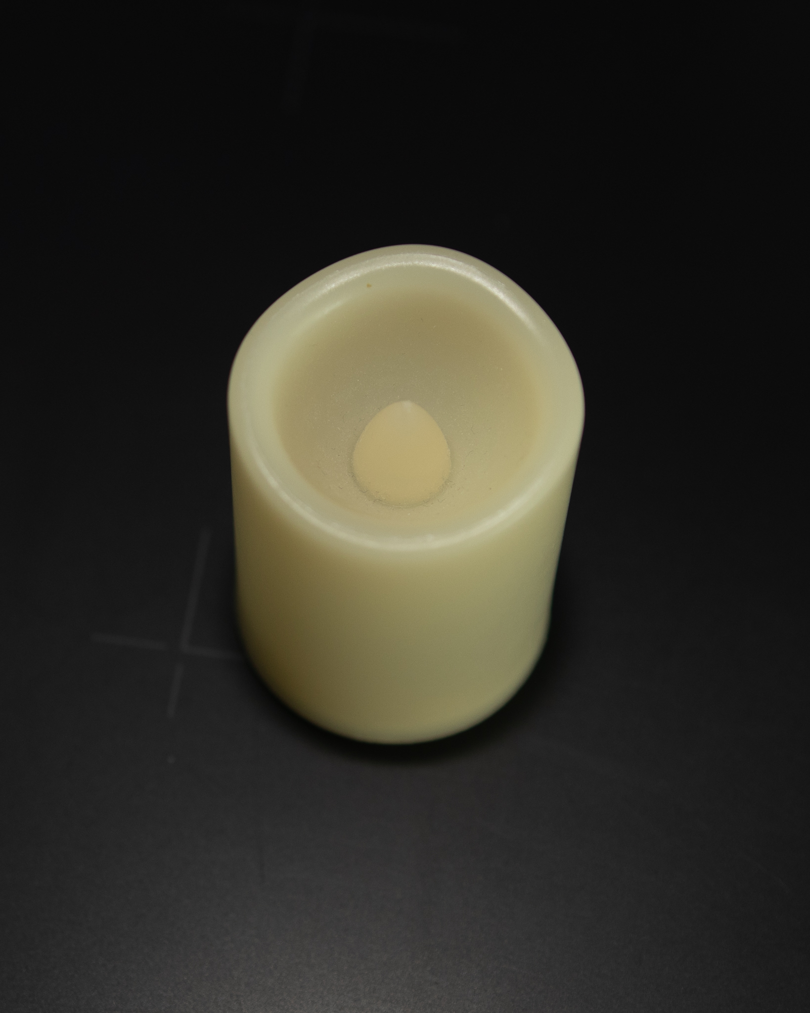
Thankfully, I didn’t have to look far to find something to learn from. A few months ago a friend of my wife gave us as a present a very cute candle holder, but since we’re renting, that’s not really a good idea. Instead I turned on Amazon (but AliExpress would have done the trick just as well) for some fake candles (LED Candles) that would do the trick. These are interesting because they are not just shaped like a candle, but they have a flickering light like one as well. Three of them in the holder fit fairly nicely and did the trick to give a bit of an atmosphere to our bedroom.

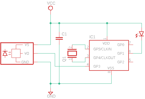
I was full ready to sacrifice one of the candles to reverse engineer it, but the base comes off non-destructively, and that the board inside is very easy to follow. Indeed, you can see the schematic of the board here on the right (I omitted the on/off switch for clarity), even though the board itself has space for more components. The whole of the candle is controlled by a microcontroller, with a PIC12F-compatible pinout (but as Hector pointed out, much more likely to be some random chinese microcontroller instead).
It’s interesting to note that the LED starts in “candle” mode once turning the switch to the “on” position, without using the remote control. My guess is that if you buy one of the versions that does not come with a remote control, you can add that functionality by just soldering a TSOP381x decoder. It also shows why the battery on these things don’t really last as long as you may want it to, despite using the bigger, rarer and more expensive CR2450 batteries. The microcontroller is powered up all the time, waiting to decode some signal from the remote control, even if the LED is off. I wanted to record the current flowing through in standby, but it’s fairly hard to get the battery in series with the multimeter — maybe I should invest on a bench supply for this kind of work.
So how does this all work? The LED turns out to be a perfectly normal warm white LED, with a domed form factor that fits nicely in the carved space in the fake candle itself, and that helps it diffuse it. To produce the flame effect, the microcontroller uses PWM (pulse-width modulation) — which is a pretty common way to modulate intensity of LEDs, and the way most RGB LEDs work to produce combined colours, just like on my insulin reminder. Varying the duty cycle (the ratio between “high” and “low” of the digital line) allows changing the intensity of the light (or of the specific colour for RGB ones). If you keep varying the duty cycle, you get a varying intensity that simulates a flame.

The screenshot you can see is from Saleae Logic software. It shows the variable duty cycle in span of a few seconds, and it’s pretty much unreadable. It’s possible that I can write code for a decoder in the Saleae logic, and export the actual waveform it uses to simulate the flickering of a flame — but honestly that sounds a lot of unjustified work: there’s not really “one” true flame algorithm, as long as the flickering looks the part, it’s going to be fine.

So, how do you generate the right waveform? Well, I had a very vague idea of how when I started, but thanks to the awesome people in the Adafruit Discord (shout out to IoTPanic and OrangeworksDesign!) I found quite a bit of information to go by — while there are more “proper” way to simulate a fire, Perlin noise is a very good starting point for it. And what do you know? There’s a Python package for it which happens to be maintained by a friend of mine!
Now there’s a bit of an issue on how to properly output the waveform in PWM — in particular its frequency and resolution. I pretty much just thrown something at the wall, it works, and I’ll refine it later if needed, but the result is acceptable enough for what I have in mind, at least when it comes to just the waveform simulation.
The code I thrown at the wall for this is only going to be able to do the flickering. It doesn’t allow for much control and pretty much expects full control of the execution — almost the same as in the microcontroller of the original board, that literally turns off the moment the IR decoder receives (or thinks it’s receiving) a signal.
I was originally planning to implement this on the Adafruit M4 Express with PWMAudioOut — it’s not audio per-se, but it’s pretty much the same thing. But unfortunately it looks like the module needed for this is not actually built into the specific version of CircuitPython for that Feather. But now we’re in the business of productionizing code, rather than figuring out how to implement it.
btw, you could/should also correct the duty cycle for perceived brightness, e.g. to achieve “half-brightness” the duty-cycle should be roughly 18% on/82% off. “Psychometric Lightness and Gamma” (https://www.photonstophotos.net/GeneralTopics/Exposure/Psychometric_Lightness_and_Gamma.htm) describes how the CIE formula for lightness is used to convert between luminance and “lightness”. I found when doing simple fading that applying the correction made the final result far more satisfying.